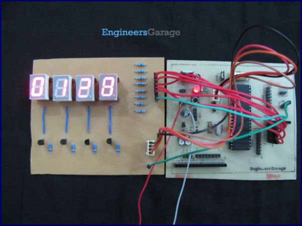
As explained earlier, a seven segment interfaced with PIC uses almost an entire port (minimum 7 pins) to display a value. But a real time application, like watch, calculator etc., usually requires at least 3-4 seven segments. In such a case it is not advisable to use a port of the controller for each seven segment. In these cases, multiplexing technique is used to work with more than one seven segment. Here multiplexing of four seven-segments has been explained with PIC18F4550 to display four-digit count from 0000 to 9999.
The data pins (a-g) of all the seven-segments are connected to a single port (Port D*) as shown in the circuit diagram. Transistors BC547 are connected to COM pins of seven-segment for switching. The switching of COM pins is controlled by four pins of PortA.
*Please note that the pins of PortD are not continuous and care has to be taken while making the connection.
The multiplexing concept is based on the principle of persistence of human vision. A human eye cannot detect a visual change if the frames change at a rate of 25 (or more) frames per sec. This means that if events occur continuously with a time difference of less than or equal to 0.04 sec (1/25 sec), then we cannot notice the transition between those events.
Considering this, the seven-segments are switched on one by one with a very small time delay. Thus, even though only one segment glows at a time, it appears that all the segments are glowing together. (See video) Thus the key factor in multiplexing is switching time of the segments.
Programming steps:
· The count value to be displayed is stored in a variable.
· Extract the individual digits from the count value into different variables.
· Turn on the seven-segments one by one with a small time delay.
· Send the hexadecimal values corresponding to individual digits to PortD.


