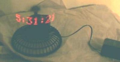
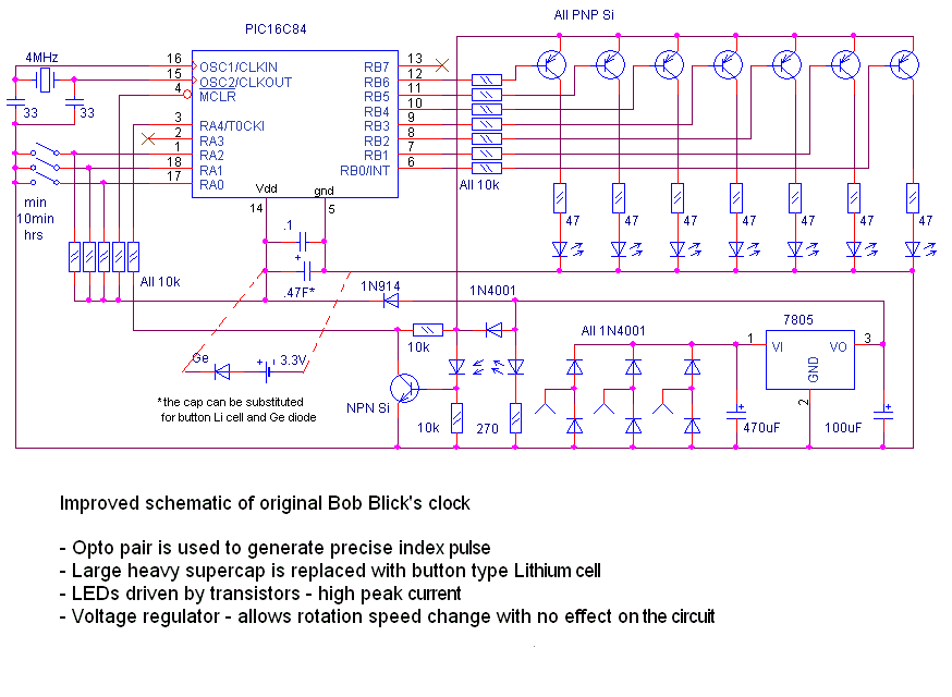
Red digits on this photo appear to float in the air in front of the clock. This illusion is based on inertia of a human eye. If LED-formed digits will periodically and frequently enough flash, they will appear solid and steady. And since the matrix of digits is formed by a mechanically scanned single line of LEDs, and the fast rotating clock body is not visible, it leaves digits “suspended” in the air. The first clock using this concept was built (and PIC microcontroller code written) by Bob Blick, please visit his page for yet more photos of his original clock and clocks built by other people.
The heart of this clock is PIC16F84 microcontroller. (Older PIC16C84 version works just fine). The microcontroller is programmed with the code provided below. If you don’t have a PIC programmer, it isn’t difficult to make one. A few parts (for a couple bucks) connected to the parallel port of your PC will program the PIC for you.
First, mechanical stuff. We will use a 12V automotive fan (sells for $12.95) as a kit, containing almost all nesessary mechanical parts. The only extra part you’ll need is a ball bearing and brass tube about 2mm in diameter. The bearing I’ve used was 22mm ext. dia., 10mm int. dia., and 6mm high. This size is not very critical, (that’s just what I had in hand) but try to find something close: this one fits very nicely.
First you’ll need to take the fan apart. The front grill and swing action mechanism parts aren’t needed. Don’t throw away the propeller yet, you will use it’s hub later.
Next step is disassembling the motor. Slide the windings and commutator along the shaft toward non-threaded end of the shaft leaving about 15mm of the shaft at this end. Be careful not to separate the commutator from the rotor windings. The easiest way to do this is to stick the commutator end of the shaft to the rear sleeve bearing (white plastic part) and just tap the shaft with a hammer to the other end, using sleeve bearing as a support. Once it’s done, you’ll need to solder a wire to the ends of three commutator segments: 2 wires to any adjacent segments, and one wire to the segment opposite the other two chosen previously.
For more detail: Build a digital clock with its digits levitating in the air using PIC16F84
The post Build a digital clock with its digits levitating in the air using PIC16F84 appeared first on PIC Microcontroller.

