Description
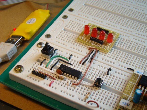
Today’s lab session is about binary counting LEDs. The binary 1 and 0 will be represented by turning LEDs on and off. You will make a 4-bit binary counter (using 4 LEDs) that counts from 0 to 15 (0000-1111 binary). The four LEDs are connected to RC0 through RC3 port pins of PIC16F688 with current limiting resistors (470Ω each) in series. A push button switch is connected to pin RC4 to provide input for the counter. The counter starts from 0, and increase by 1 every time the button is pressed. When the counter reaches 15 (all LEDs on), it will reset to 0 on the next press of the button.
Required Theory
You should be familiar with the digital I/O ports of PIC16F688 and their direction settings. If you are not, read Digital I/O Ports in PIC16F688. Read previous lab session (Lab 2: Basic digital input and output) to learn about reading inputs from a push button.
Circuit Diagram
The circuit diagram and its construction on the breadboard are shown in figures below. The PIC16F688 microcontroller uses its internal clock at 4.0 MHz.
Software
Define PORTC pins RC0-RC3 as output, and the pin RC4 as an input. Disable comparators (CMCON0=7), and configure all I/O pins as digital (ANSEL=0). Use Button() function to read input from the push button switch.
For more detail: Lab 3: Four bit binary counter using PIC16F688
The post Lab 3: Four bit binary counter using PIC16F688 appeared first on PIC Microcontroller.
