Quantcast
Channel: Clock - Timer Projects - PIC Microcontroller
Viewing all 218 articles
Browse latest View live

Sunrise Alarm Clock

$
0
0

Introduction

This report covers the design and building of a programmable alarm clock that uses a full spectrum LED to wake you up using your body’s natural response to sunlight. Rather than waking you up with an annoying alarm, a sunrise alarm clock slowly turns on a light in your room over the course of about an hour or so to simulate a natural sunrise. This allows your body to naturally wake up when it reaches the end of its current REM cycle rather than having in the middle of such a cycle (which can make waking up difficult and be disorienting). If you are still asleep at the end of the sunrise cycle, a back up audio alarm goes off to wake you up. Using a sunrise alarm clock can lead to more restful sleep, a gentler wake up experience, and make it more likely you actually stay up after waking up. For the busy student, a sunrise alarm clock can mean the difference between waking up peacefully for class, or missing class entirely after shutting off their traditional alarm and falling right back asleep without even realizing it.


High level design:

Design Requirements:

This iteration of a sunrise alarm clock had several design parameters. It needed to have a full spectrum LED to mimic sunlight. This was intended to create a pleasing light, but also to help combat Seasonal Affective Disorder. Another important thing for the LED was that it used analog dimming. PWM dimming can create an annoying flicker and we wanted a smooth light viewing experience. It would also be awesome to be able to use this fancy LED during the day or night without the the alarm functionality. We ended up calling this a “night light mode” because you could use the alarm as a “night light” if you needed to.

It also needed a backup audio alarm in case the sunrise wasn’t enough to wake you up. In this project this is a simple piezo buzzer that is very annoying and is sure to wake even the heaviest of sleepers up. For the user interface it needed to have a physical control interface. An LCD screen with buttons for sure. We ultimately decided to stick with the TFT we have been using in the lab. We also decided on a 2 button and a rotary encoder with button design for the user controls. This would allow anybody to use the alarm clock just by walking up to it and twiddling with the dials.

In addition to the physical interface, remote control of the system via a phone app through a bluetooth connection was also added. This way, you can set the alarm for the morning without having to get out of bed.

One final requirement is that the alarm clock should remember the alarm and also keep track of time even if it loses power (such as by being unplugged, or through a power outage). There is nothing worse than having a power surge in the middle of the night and oversleeping and being late because your alarm doesn’t go off in the morning. An RTC chip and EEPROM for alarm storage with on board battery backup solves both of these issues.

Logical Structure:

Below you can see a high level block diagram of the system as it is now. The PIC32 is the brain of the system and interacts with the different “modules” of the system. In the block diagram below you can see how we separated out the different modules in our design. We were able to then test each of these modules individually and put them together in the final build.

Hardware/Software Tradeoffs:

One thing that we wanted to implement in our system was hardware based input debouncing. This would make the software side of the system a lot easier to run since we would already be working with clean inputs and don’t require additional state machines to debounce the switches. However this complicates the hardware side a bit which is the tradeoff. Since we utilized software debouncing in an earlier lab this semester, we decided to try and do the hardware version.

Hardware Design

The hardware for this project can be subdivided into several submodules. We have the UART bluetooth interface, the I2C devices, the LED systems and alarm, and the user interface.

Bluetooth:

For this project we used an HM10 Bluetooth module clone (image). These modules make bluetooth connection very easy by acting as a simple serial passthrough. The PIC will send serial data to the bluetooth module, and any devices connected will receive that data via bluetooth. Any data that gets sent to the HM10 then is passed on to the PIC via UART. The HM10 module does all the heavy lifting for us.

On the control side of things we are able to use almost any modern phone to connect to this bluetooth module to control our alarm clock.

I2C:

We have two I2C slave devices in this project and they both happen to be on the same peripheral board. The DS3231 is a high precision RTC chip with temperature compensation. Using this device allows us to always have the time and continue to keep track of the time even when the alarm clock is unplugged thanks to a lithium coin cell which keeps it going. This peripheral board was connected to the clock and data lines of the PIC32’s I2C1 channel.

LED System:

There were two primary design goals of the LED system of this alarm clock. The first was to use a full spectrum LED to simulate natural sunlight, and the second was to implement analog dimming to avoid that annoying PWM flicker. The Seoul Semiconductor SunLike line of LEDs contain phosphors which combined with a violet LED are able to replicate the sun’s spectrum very closely compared to traditional LEDs. The hope is that this replication of sunlight will wake up your body easier and also help with SAD during the dark winter months in New York.

image courtesy of Seoul Semiconductor

Driving this LED is no easy task, it has a typical forward voltage of 36V so we need a fairly beefy power supply to get it working. The ODLC-45 from Meanwell is able to easily drive this LED and also has a built-in analog dimming functionality taking a 10V PWM input signal. The duty cycle of the PWM signal determines the current that the LED runs at.

image from the ODLC-45 datasheet

In addition to a driver we also need a heatsink for this large LED, so a simple Sunon LED heatsink with integrated 12v fan was used.

For the audio alarm, a simple piezo buzzer is used, it is loud and annoying enough to get anybody to wake up from sleep.

User Interface

The user interface consists of the display and the controls. We simply used the 240×320 pixel TFT that was provided at the beginning of the course. The controls consisted of two momentary switch buttons and a rotary encoder/button combination. Below is a picture of the UI concept we had planned.

One of the things that we wanted to do was implement hardware debouncing in this circuit. This would allow us to simplify the coding process since we wouldn’t need to debounce in software.

The hardware debounce is achieved through an RC network which basically smooths over the bounces. This classic charging curve is then fed into a schmitt trigger which creates a very sharp cutoff and outputs a clean signal which is then connected to the external interrupt pins.

The rotary encoder uses quadrature encoding. When the rotary encoder is turned, two pulses are emitted, each on a separate channel. If the rotary encoder is turning clockwise, the pulse on channel A leads the one on channel B. If it is turning counter clockwise the pulse on channel B leads the one on channel A. By noting which signal is detected first, the direction of rotation can be determined.

Program Design

The program that controls the alarm clock is broken into multiple protothreads. Some of these threads run continuously while others wait for a flag to change or only run in a specific state. In addition to the protothreads, each of the user interface buttons has an associated ISR that is used to toggle flags to indicate that a button has been pressed.

Protothreads:

Control Thread

This thread controls the state of every flag that doesn’t directly indicate that the state of a button or rotary encoder has changed (these flags are set in the button ISRs). The control thread is essentially a finite state machine that changes state based on the state of the flags that indicate whether the buttons have been pressed. It differs from a pure finite state machine because there are some flags that are not tied to the current state. A finite state machine seemed like the simplest choice for this thread because it allowed the effect of every button to be enumerated for every state that the clock could be in. The button flags have different behavior depending on the current state of the control thread: for example, when the TFT is displaying the default clock screen, the rotary encoder button has the effect of toggling night light mode, but when the TFT is displaying the settings screen, the rotary encoder button instead has the effect of selecting a setting to change.

Night Light Thread

This thread controls the light night mode of the alarm clock and only runs if night light mode is enabled. Night light mode lets you use the LED as a light source without needing to set an alarm, and this thread manages the dimming level of the LED and whether or not the LED is on at all.

Sunrise Thread

This thread checks the status of the sunrise mode flag. If the flag is enabled, it sends a pulse-width modulated signal to the sunrise LED, with the duty cycle of this signal being determined by the formula: 400000-(Ts*40000)/Ls with Ts being the time in seconds remaining in the sunrise and Ls being the length in seconds of the full sunrise. This has the effect of increasing the intensity of the LED linearly from zero to its maximum as time progresses from the start of the sunrise to the alarm time.

Audio Alarm Thread

If the alarm audio is enabled and the alarm is currently activated, this thread toggles the pin that controls the audio output every 500 milliseconds to produce a sound that will wake the user up if the sunrise has failed (or was not enabled).

Update Time Thread

This thread runs every 100 milliseconds. It first calls a function that queries the RTC module for the current time. Then, if the returned time is different from the currently displayed time, it updates the TFT display. If an alarm is enabled the thread checks for a match between the current time, the sunrise start time, and the alarm time. If either of the latter two match the former, then the flags for starting the sunrise or starting the alarm sound are set depending on what alarm settings have been enabled.

BT Serial Thread

The BT serial thread only activates when a serial command is received. Its job is to parse the command and perform any operations if required. There are currently 6 commands that it recognizes.

  • Toggling the TFT Backlight
  • Toggling the alarm enable
  • Set alarm to the received data
  • Send out alarm data
  • Set the night light level
  • Toggle the Night Light
  • With these commands, the associated phone app is able to control the alarm clock remotely.

Interrupt Service Routines:

The interrupt service routines for the buttons were very simple. All they did was set two global flags and clear the interrupt. They set the flag for their associated button and also the flag for an input change which activates the control thread.

The interrupt service routines for the rotation of the rotary encoder were a bit more complex. They need to first check the flag for the other rotary encoder channel to see if the interrupt for the other channel was triggered first. If it was, then the ISR knew the direction of rotation and saved it. If it did not see that the other channel was triggered, it would simply set the flag for its own channel and clear the interrupt.

One additional check needs to happen though. It can occasionally happen that the inputs are misread if the rotary encoder is spun too quickly, and one of the pulses gets missed. When this happens suddenly the program thinks the encoder is spinning the other direction since it thinks the other channel arrived first. This is solved by making the ISR check how long it has been since the last interrupt, and if it is greater than the timeout, 100ms in this case, it simply resets both rotary encoder flags to ensure the correct direction is read in the future.

Main Program

The purpose of the main function is simply to set up all the input and output pins, activate the serial and I2C channels, and intialize and start the protothreads.

Phone App:

The phone app was programmed using MIT App Inventor. This allowed a rapid development of the basic functionality required. The phone app is basically a wrapper for the serial commands that can be sent to the serial thread through the bluetooth module:

  • Toggling the TFT Backlight
  • Toggling the alarm enable
  • Set alarm to chosen settings
  • Get the current alarm data
  • Set the night light level
  • Toggle the Night Light

I2C Utility Functions

The I2C communication with the RTC module and EEPROM uses the communication patterns defined in the spec sheets for those components. The PIC32 has I2C communication functions and status bits defined in the legacy peripheral librariesThe main problem encountered when sending bytes to the I2C modules from the PIC32 was difficulty checking for acknowledgement from the modules. This was solved by waiting for the transaction to be complete before checking acknowledgement (this is not done by default when acknowledgement is checked). The PIC32 likely was checking for acknowledgement before the transaction was complete (plausible considering that the PIC32’s clock is many times faster than the selected I2C clock).

Several utility functions were written in order to make communication with these two modules easy. Since only four types of transactions (set RTC time, retrieve RTC time, save bytes to EEPROM, retrieve bytes from EEPROM) were ever performed, a function was written for each transaction and stored in a file that was included in the main file.

Results of the Design:

Our alarm clock system works very well. The user interface functions exactly as intended, and the buttons are effectively debounced. The phone app works just as intended as well. You can lay in bed and change the alarm settings as desired. A cardboard box enclosure was used for simplicity and to reduce cost. The LED heatsink stays cool and only gets slightly warm when the LED is powered on at full power for extended periods of time.

For a demo of the alarm clock watch the video below:

One other thing of note: It is possible for the time value of the clock to be incorrect for a fraction of a second. This is because the PIC32 polls for the current time every tenth of a second and then updates the displayed time on the TFT. If a time update occurred on the RTC module immediately after it was polled for the time, the value on the clock would be incorrect until the next poll occurred and was displayed. The below diagram illustrates an example of this behavior: the “clk” line is a simple clock that toggles from 0 to 1, the “poll” line represents the polling of the RTC by the PIC32 (occuring at a different frequency than the clock), and the “disp” line represents the displayed value on the TFT. With an ideal clock, the value of the disp line would always match that of the clk line, but because of the limited nature of the polling, this is not true in several regions on the diagram. This is an extreme example of innacuracy rising from polling, and it would be greatly reduced in severity by polling at a higher frequency than the clock, but it successfully illustrates the phenomenon.

Conclusions:

This design and final product met all of the required needs of our sunrise alarm clock specifications. Our goal was to create an alarm clock that emulated the rising of the sun in order to wake up the user, and our project achieves that. It is easy to use, the phone app works seamlessly, and this alarm clock is likely to be used for a long time going into the future.

It wasn’t all perfect though. In order to reach this point we did have to cut out some original intended features. In our proposal we had planned to have 5 separate programmable alarms that were stored in the eeprom. We also planned on being able to set which days of the week they would activate and reset automatically. Due to time constraints this more advanced alarm clock feature was cut to make sure we got a functioning unit at the end our our project.

Another interesting thing that we had happen had to do with the rotary encoder. When spun quickly, it is possible for the PIC32 to miss a pulse due to the debouncing circuit and make the PIC32 think the encoder has been spun in the opposite direction to the actual spin. This is a limitation of the quadrature encoding. The original plan was to utilize a grey code based encoder where this type of error is far less likely to happen. However due to an ordering error and again a time limitation, we needed to make do with the encoder we had.

Overall this project turned out to be success and while our end product is missing a feature or two, it still functions excellently and will be used for a long time.

Appendix A: Releases

The group approves this report for inclusion on the course website.

The group approves the video for inclusion on the course youtube channel.

Appendix B: Commented program listing

The program consists of the source files below:
Config_1_3_2.h
Glcdfont.c
Pt_cornell_1_3_2.h
Tft_gfx.h
Tft_gfx.c
Tft_master.h
Tft_master.c
Control.h
Control.c
Data.h
Data.c
I2c.h
I2c.c
types.h
Main.c
Screens.h
Screens.c

Appendix C: Schematic

Source: Sunrise Alarm Clock

The post Sunrise Alarm Clock appeared first on PIC Microcontroller.


LED Binary Clock using PIC16F628A microcontroller

$
0
0

LED Binary Clock

This is the second revision of my PIC based LED binary clock. The original version was the first PIC project I attempted, it used a PIC16F84A to do both the timekeeping and control the display matrix, unfortunately it didn’t keep good enough time and gained about a minute every week.
LED Binary Clock

This second version is based around a PIC16F628A running at 4MHz to control the display, it also uses a DS1307 realtime clock chip to do the timekeeping. Every second the DS1307 sends a pulse to the PIC chip, the PIC then reads the internal time from the DS1307 over the I2C bus and then displays the time in binary on the LED display.

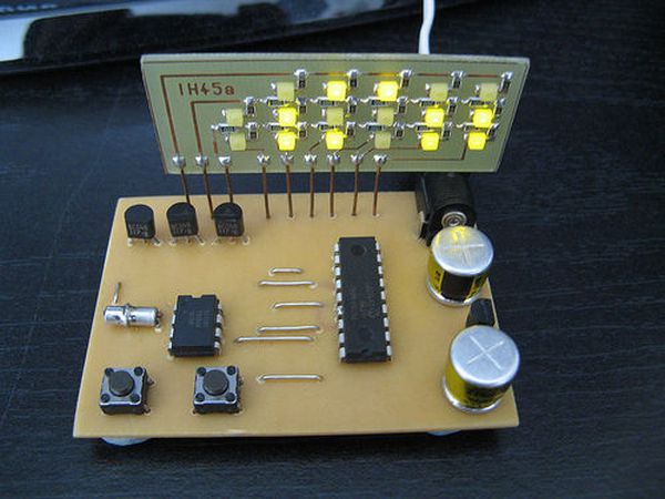
The bottom row of LEDs display the seconds, the middle rows shows the minutes and the top row is for hours. The time displayed in the picture is 01100:010011:011011 or in decimal 12:19:27. The time is in 24 hour format so goes up to 10111:111011:111011 or 23:59:59

The PCB could be made double sided, or as I have done here single sided with 7 wire links soldered in place instead of the top copper layer. It has a 5 volt regulator so could be powered from any 9 – 15 volt DC power supply.

Step 1: Parts / Tools

As well as basic PCB making and soldering equipment you will need the following components:

1x PIC16F628A & programmer
1x DS1307 realtime clock chip
1x 32.768kHz watch crystal
3x BC548 (or similar) transistor
2x PTM pushbuttons
1x 78L05 regulator
2x 220uF electrolytic capacitors
17x Surface mount LEDs
1x DC power jack socket
5x 4.7K surface mount resistors
8x 100 ohm surface mount resistors
1x 2k surface mount resistor
12x zero ohm links (Or 11 zero ohm links and CR2016 backup battery)
1x 100nF surface mount capacitor
50cm single stranded bell wire
1x 9v – 15v DC power supply with DC jack

Step 2

Make PCBs & Program PIC

Make PCBs & Program PIC

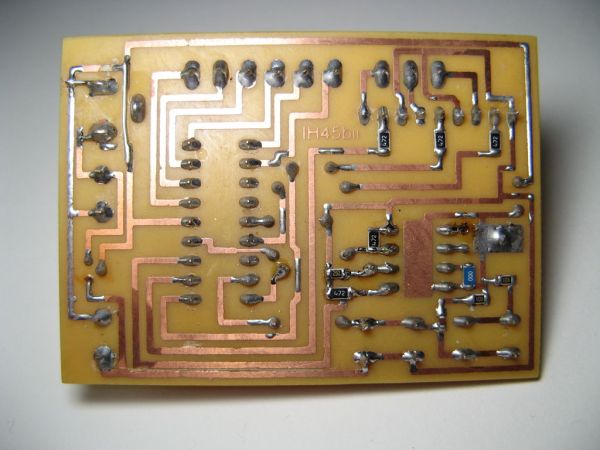
The first step is to make the PCBs, the PCB layout and schematics for the main clock and the display board are provided in Eagle format. The clock PCB is double sided, but the top layer consists simply of 7 links, this means that the PCB could also be made as a single layer with 7 wire links instead, this is the way I chose to make it as I cannot make double sided boards.

The display PCB uses exclusively surface mount devices while the main clock PCB uses a mixture of surface mount and through-hole components.

It is important to program the PIC chip with the hex file prior to soldering into the circuit as there are no ICSP connections on the board.

Step 3

Solder bottom components

Solder the 8 resistors, 1 capacitor and the zero ohm link / backup battery as shown to the bottom side of the main clock PCB.

Step 4

Solder top components

Next solder the through hole components ensuring to orientate the 2 chips, the 2 capacitors and the regulator correctly.

For more detail: LED Binary Clock using PIC16F628A microcontroller

The post LED Binary Clock using PIC16F628A microcontroller appeared first on PIC Microcontroller.

A 12hr/24hr LED Clock with display control using PIC16F628A microcontroller

$
0
0

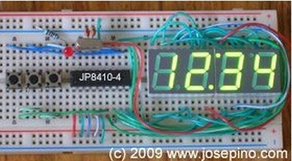
This LED clock may not be the easiest to build but surely it is the one with fewer parts that you can find, for that reason I call it “The ANP LED Clock”. (ANP stands for Almost No Parts.)

Using the micro controller PIC 16F84A or the 16F628 (same pinout), this clock have more and improved features than my previous LED Clock.

Here are the features on this ANP LED Clock:

LED Clock with display control

  • Can use common cathode or common anode 7-segment LED displays.
  • Displays time as 12 hours or 24 hours format.
  • Allows to enable or disable the display for battery-operated circuits.
  • Can control the display brightness to reduce power consumption
  • 7-segment LED displays are charlieplexed to reduce I/O ports usage.
  • PM LED indicator (optional)
  • Only 10 parts needed: 1 PIC 16F84A, 2 22pF Capacitors, 2 n.o. switches, 1 4Mhz Xtal and 4 CA or CC 7segment LED displays.
  • Operates from 2.5 to 5.5 Volts, it can even work with a 3V coin batteryBecause all this features, the applications for this ANP LED Clock could be:
  • Inexpensive LED Clock to replace the expensive broken one from your luxury car.
  • “vintage” LED wristwatch – Using some LED display from old calculators and 3 Volts coin battery, it’s possible to build a small clock.
  • Jumbo Clock – Non-inverting buffers can be used to drive more voltage and lit giant 7-segment led displays.
  • Compact clock for your appliances or projects


Even more:

Desktop Clock as gift for a friend

  • Nice clock to keep your 4-years old niece distracted for a while
  • A piece of trash after your 4-years old niece were playing with the clock.


Let’s get technical, here is the pin out information for this project:
Pin 1 to VDD for 12Hrs, VSS for 24Hrs
Pin 2 to VDD C Anode display, VSS for C Cathode
Pin 3 to VDD Enable display, VSS disable display
Pin 4 to VDD Normal operation, VSS Reset
Pin 5 VSS Ground or
Pins 6..13 To multiplexed display
Pin 14 VDD or +
Pins 15 & 16 Xtal Oscillator (4Mhz only)
Pin 17 to Display Decimal Point
Pin 18 PM LED indicator (optional)
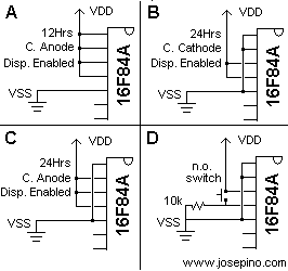
Here are some examples how configuration pins are wired:
Figure A: For 12 Hours LED clock using Common Anode 7-segment LED displays.
Figure B: For 24 Hours LED Clock using Common Cathode 7-segment LED displays.
Figure C: For 24 Hours LED clock using Common Anode 7-segment LED displays.
Figure D: For Battery operated clocks, a 10k resistor and a switch can be used to view the time, specially for wrist watches.
Here is the schematic for the ANP 12/24 Hrs LED Clock:
ANP LED Clock with display control
Please note the PM LED indicator and the Brightness control switch are optional.
Bill of materials:1 PIC 16F84A with JP8410-a software
1 Xtal 4 Mhz
2 22pF ceramic capacitors
2 n.o. micro switches.
4 7-segment LED displays (CA or CC)
Optional:1 LED for PM indicator
1 4.7k resistor
1 n.o. microswitch for brightness control.

Notes:

1.- Before applying power to the circuit, set the configuration pins to the one desired. DO NOT APPLY POWER without connecting pins 1, 2 & 3.

2.- Device configuration: CP Off, WDT Off, PWRTMR ON, OSC Xtal.

This project may not be suitable for Giant LED Displays because the charlieplexing process
 How it Works:
The displays are “Charlieplexed” and controlled with modulated pulses, also know as PWM (Pulse width modulation). There are no resistors on most of my projects because I limit the current using the software instead of using resistors. Also, I do use the internal pull-ups from the microcontroller PIC itself. The 1-second routine is similar to the one used by Roman Black but not the same. To keep accuracy, connections to the XTAL and 22pf capacitors must be as short is possible. Read the specifications from the Xtal manufacturer.
Here is a video showing how it works:

The post A 12hr/24hr LED Clock with display control using PIC16F628A microcontroller appeared first on PIC Microcontroller.

VIRTUAL HOURGLASS TIMER

$
0
0

INTRODUCTION

Time-keeping is inherently stressful, especially when you can see the seconds ticking down. The Virtual Hourglass Timer takes all the pressure away through its relaxing visual display.

Inspired by this digital hourglass alarm clock , the Virtual Hourglass Timer allows the user to set a timer and opts to display the time remaining in an hourglass format instead of the traditional hours, minutes, and seconds approach. The hourglass allows users to check the time remaining with a quick glance at the display, instead of having to closely read their phone or other digital timers. In addition, the Virtual Hourglass Timer iPhone application allows users to easily set timers via Bluetooth, giving users even more flexibility. For example, a user could be cooking and set a timer to remind them to take the food out of the oven; when their hands are full with other meal prep, a quick glance at the digital hourglass could let them know how much time is left without having to drop what they are doing to check their phone.

The Virtual Hourglass Timer is powered by a PIC32, an Arduino UNO, an Adafruit Bluefruit LE SPI Friend, and a TFT display. It can be controlled via our iPhone application.

STARTING CHALLENGES

Our two biggest challenges at the start of our product development were a malfunctioning LED matrix display and a difficult-to-use Bluetooth module.

LED MATRIX

After we received the LED matrix, we referred to the data sheet and several examples online to connect the display and run starter code on it. Unfortunately, even example code from the vendor was not driving the display correctly. Ultimately, we concluded the hardware was damaged and due to time restrictions, we decided to use the TFT LCD display from previous labs as our main timer display. While this certainly was not ideal, we believe it was enough to show proof of concept.

ADAFRUIT BLUEFRUIT LE SPI FRIEND

We initially tried to have the Big Board and the BLE module communicate directly. After hours of unsuccessful attempts, it came to our attention that in order to establish this communication channel, we would have to write the entire SDEP (SPI Data Transport) layer code. After discussing the issue with Bruce Land, we were allowed to use an Arduino UNO, and by extension the vast SPI Friend Arduino support, to facilitate this process.

DESIGN, IMPLEMENTATION, AND TESTING

For our project, we decided to build off of one of the suggested project ideas from the course website. This project seemed doable within the given timeframe and would involve heavy usage of the PIC32, which we felt was ideal for a project for this class. Our project can be be broken down into a few major components:

  • Animation
  • Custom Command Set
  • UART
  • Bluetooth
  • Additional Threads

Additional hardware, outside of the PIC32, includes a TFT Display, an Adafruit Bluefruit LE SPI Friend, and an Arduino UNO. The role of each of these components will be discussed further as we break down the project piece by piece.

ANIMATION

Our project utilizes the TFT display used in Lab 2 to animate an hourglass filled with sand. The basis of our animation code is the animation code from lab 2. We began with our ball collision code from the lab and altered it as necessary to model grains of sand. In the end, we were able to fill the top half of the hourglass with sand, then periodically drop grains down to the lower half to simulate sand falling down an hourglass as time passes. The rate at which these grains drop is determined by the amount of time that the timer is set for.

HARDWARE

The only hardware needed for this section is the TFT display, which connects directly to the Big Board. The PIC32 communicates with the TFT display using SPI.

SOFTWARE

The animation code in our project was very software intense. We began with the animation code from Lab 2 as the basis for our code and worked from there. We began by creating a function called DrawHourglassSmall() which uses multiple calls to tft_drawLine() to draw the hourglass on our display.


void drawHourglassSmall(void) {
    // top border
    tft_drawLine(80, 40, 160, 40, ILI9340_BLUE);
    // top side wall
    tft_drawLine(80, 40, 80, 80, ILI9340_BLUE);
    // top side wall
    tft_drawLine(160, 40, 160, 80, ILI9340_BLUE);
    // bottom border
    tft_drawLine(80, 160, 160, 160, ILI9340_BLUE);
    // bottom side wall
    tft_drawLine(80, 120, 80, 160, ILI9340_BLUE);
    // bottom side wall
    tft_drawLine(160, 120, 160, 160, ILI9340_BLUE);
    // top angle in
    tft_drawLine(80, 80, 110, 90, ILI9340_BLUE);
    // top angle in
    tft_drawLine(160, 80, 130, 90, ILI9340_BLUE);
    // bottom angle in
    tft_drawLine(80, 120, 110, 110, ILI9340_BLUE);
    // bottom angle in
    tft_drawLine(160, 120, 130, 110, ILI9340_BLUE);
    // tube wall
    tft_drawLine(130, 110, 130, 90, ILI9340_BLUE);
    //  tube wall
    tft_drawLine(110, 90, 110, 110, ILI9340_BLUE);
}
					

This function is called each time our animation thread runs in order to redraw the hourglass in case any of the grains of sand drew over the hourglass.
The grains of sand are items from our balls array, which is a 2D array. The first index represents the grain of sand we are referring to, and the second index represents the field of that grain of sand we wish to access. Each grain of sand has the following fields: xc, yc, vxc, vyc, and spawn_time . The xc and yc fields represent the x and y coordinates of the grains of sand while xvc and vyc represent the x and y velocities of the grain of sand. The spawn_time field is used if we wish to delay when the balls spawn relative to each other. In the end, we decided to spawn all the balls at the same time, so they were all given a value of 0. The function ball_init() is used to initialize all the grains of sand. This function erases the grains from their current position and updates their fields to the spawn positions of each grain of sand. This function is called each time our timer receives a command to start the timer or a command to cancel the timer (that way the grains of sand are erased from the screen).


void ball_init(void) {
    // init balls
    int k;
    for (k = 0; k < num_balls; k++) {
        tft_fillCircle(Accum2int(balls[k][xc]), Accum2int(balls[k][yc]), BALL_RADIUS, ILI9340_BLACK);
        live[k][0] = TRUE;
        live[k][1] = 0;
        balls[k][xc] = int2Accum(spawn_xc + ((k * 6) % 60));
        if (k < 10) balls[k][yc] = int2Accum(spawn_yc);
        else if (k < 20) balls[k][yc] = int2Accum(spawn_yc - 6);
        else balls[k][yc] = int2Accum(spawn_yc - 12);
        balls[k][vxc] = int2Accum(spawn_vxc);
        balls[k][vyc] = int2Accum(spawn_vyc);
    }
}
					

The animation thread begins by calling the DrawHourglassSmall() function in order to start our display and draw the hourglass on it. Next is a while loop to check that the system is out of standby mode and that the grains have been initialized. We update the variables standby and init to represent these conditions. Inside the while loop, we erase each grain, update its coordinates, and then redraw the ball at its new position. This is done for every grain. Positions are updated based on a few checks. First, we check if it is time to drop a new grain to the lower half of the hourglass. To do this, we compare the values of the variables hourglass_time and drop_time , which represent the amount of time that has passed on the timer and the amount of time between sand drops respectively. The following check in the animation thread updates a boolean drop under two conditions. The first check is to make sure we have passed the amount of time we want to drop a grain of sand. This means that if we want to drop a grain every two seconds, that we do not want to drop the first grain until two seconds has passed. Without this check, a grain will always be dropped at time hourglass_time = 0 which is not what we desire. The second check performs a modulus of hourglass_time and drop_time in order to see if it is time to drop a new grain of sand. Once again, if we desire to drop a grain every two seconds, then we do not want to drop a grain at time hourglass_time = 5 . In that case, hourglass_time % drop_time = 1 and we will fail the if condition, leaving drop = FALSE .


if (hourglass_time >= drop_time && hourglass_time % (int) drop_time == 0) drop = TRUE;
					

We also select pseudo-random vxc and xc values to assign to a grain that we may drop in this loop. This is because if all of the grains were to drop with identical xc and vxc values, they would stack on top of each other and not emulate real sand. We select these values by with the statement


int mod = begin_time % 30;					
					

where mod is used as an index into two, size 30 arrays that each contain a set of potential xc and vxc values.

We decide to drop a ball based on the following conditions:


if (drop == TRUE && ball_dropped == FALSE && drop_dex < num_balls && i == drop_dex) ...
					

The drop == TRUE statement is used to determine if we are on the appropriate second to drop a grain. ball_dropped == FALSE determines whether or not we have already dropped a grain this second (since the thread is running faster than once per second). This value is changed to TRUE after a grain is dropped and is reset to FALSE when we increment hourglass_time at the start of a new second. The drop_dex < num_balls check is used to make sure that we are not trying to drop more sand than we have on screen. The drop_dex variable is incremented each time we drop a grain and is reset upon receiving a new start command. The num_balls field is used to track how many grains we are going to draw on the screen. The default value is 30, but if the timer is being set for a value less than 30 seconds, then we will draw a sand equal to the number of seconds and drop one grain per second. The final check is that i == drop_dex where is the index of the current grain of sand. When dropping a grain of sand, we only want to drop the grain that the loop is currently handling. Otherwise, the grain will have its position updated but will never be erased from its prior position, leading to grains dropping down, but never being removed from the top half. We update a dropping grain’s position as follows:


balls[drop_dex][yc] = 115;
balls[drop_dex][xc] = xcord;
balls[drop_dex][vyc] = spawn_vyc;
balls[drop_dex][vxc] = x_vel;
ball_dropped = TRUE;
drop_dex++;
					

If the grain is not dropping, then we simply set the grain’s new x and y coordinates to be equal to the sum of the prior coordinates and the x and y velocities:


 balls[i][xc] = balls[i][xc] + balls[i][vxc];
 balls[i][yc] = balls[i][yc] + balls[i][vyc];
					

Next, each grain is checked for collisions. First, for collisions with the hourglass. If a grain collides with either side wall of the hourglass then the x-velocity is negated and damped to one tenth the original value. This damping factor is added because sand does not bounce all that much. If a grain manages to collide with the top of either half, then the y-velocity is negated and damped as well. This behavior is unlikely since every grain spawns with a downwards velocity and experiences downward gravity when not resting. If a ball collides with the floor of either the top or bottom half, then the x and y velocities are set to 0 and gravity is not factored in. We remove gravity in these cases to keep the balls from moving down a pixel each loop, eventually leaving the hourglass.


// Check border collision
// Top half of hourglass
if (balls[i][yc] < int2Accum(95)) {
    if (balls[i][yc]<(40)) balls[i][vyc] = -0.1 * balls[i][vyc];
    if (balls[i][yc]>(75)) {
         balls[i][vyc] = 0
         balls[i][vxc] = 0;
    }
    else balls[i][vyc] = balls[i][vyc] + g;
} // Bottom half of hourglass
    else if (balls[i][yc] > int2Accum(105)) {
        if (balls[i][yc]<(110)) balls[i][vyc] = -0.1 * balls[i][vyc];
        if (balls[i][yc]>(155)) {
            balls[i][vyc] = 0;
            balls[i][vxc] = 0;
       }
       else balls[i][vyc] = balls[i][vyc] + g;
}
					

After checking border collision, we check sand to sand collisions. These collisions are split into two cases: head on collisions and angled collisions. In the case of a head on collision, we swap the x and y velocities of the grains and add a damping factor of 0.5 to the x velocities and a factor of 0.1 to the y velocities.


if (rij2 < int2Accum(1)) {
     _Accum temp = 0.5 * balls[i][vxc];
    balls[i][vxc] = 0.5 * balls[j][vxc];
    balls[j][vxc] = temp;
    temp = 0.1 * balls[i][vyc];
    balls[i][vyc] = 0.1 * balls[j][vyc];
    balls[j][vyc] = temp;
}
					

In the case of an angled collision, we compute changes in velocity as follows:

We make some slight adjustments to this calculation, such as adding the damping factors mentioned before and, instead of sending colliding grains away from each other, they both receive positive changes in y velocity and will thus fall down together. This change is made because if a grain lands on a pile of other grains, it should not bounce upwards. In code, this is seen as:


else {
    _Accum vxi = balls[i][vxc];
    _Accum vyi = balls[i][vyc];
    _Accum vxj = balls[j][vxc];
    _Accum vyj = balls[j][vyc];
    _Accum vDeltX = vxi - vxj;
    _Accum vDeltY = vyi - vyj;
    _Accum nDeltX = deltX;
    _Accum nDeltY = deltY;
    _Accum dot = deltX * vDeltX + deltY*vDeltY;
    _Accum nDot = dot / rij2;
    _Accum deltVx = -nDeltX * nDot;
    _Accum deltVy = -nDeltY * nDot;
    balls[i][vxc] = 0.5 * (balls[i][vxc] + deltVx);
    balls[i][vyc] = 0.1 * (balls[i][vyc] + deltVy);
    balls[j][vxc] = 0.5 * (balls[j][vxc] - deltVx);
    balls[j][vyc] = 0.1 * (balls[j][vyc] + deltVy);
}
					

Finally, we draw the grain at its new x and y coordinates. The thread will either remain in the while loop if the timer is still running, or exit the while loop and finish the thread if the system has been put into standby or the balls need to be re-initialized.

CUSTOM COMMAND SET

For this project, we devised a simple command set to communicate between our app and the PIC32. The first character of the command set is the command itself. Depending on the command, the character will then be followed by a set of digits. Finally, the ending character is an ‘e’ which signals the end of the command. Here is our command set:
‘S’: The ‘s’ character signals a start command. It is then followed by the amount of seconds the timer is to be set for. Finally, there is an ‘e’ to end the command. For example, to start the timer for 30 seconds, the command “s30e” would be sent from the app to the PIC32. This command is only sent from the app to the PIC32.
‘P’: The ‘p’ character signals a pause command. This command is sent from the app to the PIC32 in the form “pe”. This command pauses the timer.
‘R’: The ‘r’ character signals a resume command. This command is sent from the app to the PIC32 in the form “re”. This command resumes the timer.
‘C’: The ‘c’ character signals a cancellation command. This command is sent from the app to the PIC32 in the form “ce”. This command cancels the current timer and resets the timer.
‘T’: The ‘t’ character signals a time update command. This command is sent from the PIC32 to the app in the form “txxe” where the “xx” is the amount of time remaining on the timer. This command is used to keep the timer app and PIC32 timer in sync.
‘F’: The ‘f’ character signals a finish command. This command is sent from the PIC32 to the app in the form “fe”. This command is used to tell the app that the timer has finished.
In our PIC32 code, we have a command thread that handles each of the possible commands it can receive. At the start of the command thread, we first check to see if the command we have received is different from the previous command. This is because we send commands continuously in case a command is missed.


int ii;
int diff_cmd = FALSE;
for (ii = 0; ii < 30; ii++) {
    if (cmd[ii] != cmd_p[ii]) diff_cmd = TRUE;
}
					

Once it is determined that the commands are different, this thread enters a while loop under the condition that diff_cmd = TRUE . Inside this loop, the thread will check cmd[0] in a switch statement.
If the received command is a start command, the thread will search cmd for the index of the ‘e’ character. Between this index and index 0 lies the amount of time that the timer needs to be started for (in seconds). We splice the cmd string between these two indexes using the slice_str() function.


void slice_str(const char * str, char * buffer, int start, int end) {
    int j = 0;
    int i;
    for (i = start; i < end; ++i) {
        buffer[j++] = str[i];
    }
    buffer[j] = 0;
}
					

With the use of this function, the time_string variable now holds a string of the time in seconds that the timer needs to start for. The time is extracted from the string and converted to an int using sscanf() and is stored in input_time .


sscanf(time_string,"%d", &input_time);
					

This thread now sets the fields needed to run the timer. hourglass_time is restarted and the amount of sand is set (max of 30 grains, and only use less than 30 grains if the time is less than 30 seconds). Next, the drop time is calculated and set, the grains are initialized, and drop_dex is reset. Finally, our semaphore values are updated ( init standby fin diff_cmd ). init represents if the sand has been reset ( ball_init has been called). standby represents if the system is in standby mode and is used to determine whether or not the sand should be animated. fin represents if the timer has finished. When this field is true, the PIC32 sends a ‘finished’ command to the app. diff_cmd is set to FALSE in order to exit the while loop to compare the next command to the command that was just processed.


case 's':
    for (ii = 0; ii < 30; ii++) {
        if (cmd[ii] == 'e') end_idx = ii;
    }
    input_time = 0;
    char time_string[30];
    slice_str(cmd, time_string, 1, end_idx);
    sscanf(time_string,"%d", &input_time);
    hourglass_time = 0;
    if (input_time < NUM_BALLS) num_balls = input_time;
    else num_balls = NUM_BALLS;
    drop_time = input_time / num_balls;
    ball_init();
    init = TRUE;
    drop_dex = 0;
    standby = FALSE;
    fin = FALSE;
    diff_cmd = FALSE;
    break;
					

In the case of a pause command, the system simply enters standby mode. diff_cmd is once again reset for the aforementioned reasons. This will happen in every case.


case 'p':
    standby = TRUE;
    diff_cmd = FALSE;
    break;
					

resume command takes the system out of standby mode.


case 'r':
    standby = FALSE;
    diff_cmd = FALSE;
    break;
					

cancel command puts the system into standby mode and re-initializes the ball. init is set to FALSE and hourglass_time is reset since the timer is no longer running the last start command.


case 'c':
    standby = TRUE;
    diff_cmd = FALSE;
    init = FALSE;
    hourglass_time = 0;
    ball_init();
    break;
					

Finally, there is a default case that simply sets diff_cmd = FALSE .


Default:
    diff_cmd = FALSE;
    break;
					

UART

To establish communication between the Arduino UNO and the Big Board, UART serial communication was used. To set up serial communication between these two devices, we created a serial thread – which is discussed below – along with the following hardware.

HARDWARE

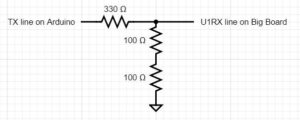
For this part of the project, the only necessary additions were the wiring between the Big Board and the Arduino to establish serial communication and a voltage divider. We wired the transmit line of the Arduino through a voltage divider and then to the receive line on the board because of the voltage output differences between the two devices. We also added the UART to USB serial cable as in Lab 3 to enable us to use PuTTY, which was used to see the input and output commands received and transmitted by the Big Board. This required three pin connections: GND, RX, and TX which were connected to GND, RA1, and RB10 respectively. The other end of this device is a USB which was simply connected to the lab computer. After reading which COMM port that USB was connected to, we opened a PuTTY serial connection to that port.

Arduino Big Board
RX pin 0 U1TX pin RB7
TX pin 1 U1RX pin RB13
GND GND

Note that the TX to U1RX connection goes through a voltage divider because of the voltage output differences between the Arduino and the Big Board.

SOFTWARE

To establish serial communication between the Arduino and the Big Board, we set up UART serial communication in mode 2, which is machine mode. We do so by adding an interface to UART1 – called in our code AUX UART. The AUX interface is only suitable for machine to machine communication because it supports DMA send/receive only, which is why we use it for communication between the Arduino and the Big Board. The following serial aux thread was created to support this interface.


// semaphores to sync threads
int ready_to_send = 1, ready_to_receive = 0;
// ========================================================
// AUX uart loopback receive thread
static PT_THREAD(protothread_serial_aux(struct pt *pt)) {
    PT_BEGIN(pt);
    // termination for machine buffer on AUX channel
    // terminate on 'e'
    PT_terminate_char_aux = 'e';

    while (1) {
        // wait for data transmission start
        PT_YIELD_UNTIL(pt, ready_to_receive == 1);
        ready_to_receive = 0;
        // get sent data on AUX channel (UART1 loopback)
        PT_SPAWN(pt, &pt_DMA_input_aux, PT_GetMachineBuffer_aux(&pt_DMA_input_aux));

        // reset semaphore to indicate data received
        // (or timed out)
        ready_to_send = 1;

        // NEVER exit while
    } // END WHILE(1)
    PT_END(pt);
} // aux uart thread
					

Before the thread, we initialize semaphores ready_to_send and ready_to_receive to be able to synchronize the serial threads. We set a termination character to signal when to stop reading the receive buffer. In our case, that termination character is ‘e’. We then yield until there is data to receive – indicated by the semaphore ready_to_receive . When there is data to be received, we spawn the machine buffer aux thread, which reads the data in the machine buffer, and put that data in the DMA input aux channel. The last thing to do is to reset the semaphores to indicate that the data has been received.
In addition to this thread, we also created a serial thread that enabled us to use PuTTY to visualize the commands that the Big Board was sending and receiving. We also handle transmission of commands from the Big Board to the Arduino and copy the commands in the aux buffer to the actual serial buffer in this thread.


static PT_THREAD(protothread_serial(struct pt *pt)) {
    PT_BEGIN(pt);
    // static char cmd[30], cmd_p[30], t0;
    static float value;
    static int i;
    static int mode = 2;
    static int v1, v2;

    // termination for machine buffer
    PT_terminate_char = '\r'; 
    PT_terminate_count = 0;
    // time in milliseconds!
    PT_terminate_time = 1000;

    while (1) {
        if (mode == 2) {
            PT_SPAWN(pt, &pt_DMA_input, PT_GetMachineBuffer(&pt_DMA_input));
        }
        // spawn a print thread        
        PT_SPAWN(pt, &pt_DMA_output, PT_DMA_PutSerialBuffer(&pt_DMA_output));
        // read a string into the aux send buffer
        sscanf(PT_term_buffer, "%s %s", "t120e", PT_send_buffer_aux);
        //send a string by loopback thru UART1 (AUX))
        // wait for the read to be done
        PT_YIELD_UNTIL(pt, ready_to_send == 1);
        // start the read, THEN start the write
        // signal the receive thread that data is coming
        ready_to_receive = 1;
        // clear the ready flag until read thread is done
        ready_to_send = 0;
        // wait a little so that receive thread is ready
        // and the DMA channel is ready
        PT_YIELD(pt);
        if (msg_ready == TRUE && fin == FALSE) {
            sprintf(PT_send_buffer_aux, "t%de", hourglass_time);
            // send using AUX UART 
            PT_SPAWN(pt, &pt_DMA_output_aux, PT_DMA_PutSerialBuffer_aux(&pt_DMA_output_aux));
            msg_ready = FALSE;
        } else if (msg_ready == TRUE && fin == TRUE) {
            sprintf(PT_send_buffer_aux, "fe");
            // send using AUX USART 
            PT_SPAWN(pt, &pt_DMA_output_aux, PT_DMA_PutSerialBuffer_aux(&pt_DMA_output_aux));
            msg_ready = FALSE;
            standby = TRUE;
        }
        // wait for the AUX receive to actually happen
        // (including time outs)
        PT_YIELD_UNTIL(pt, ready_to_send == 1);

        // test for AUX channel timeout otherwise
        // copy the data
        if (PT_timeout_aux == 1) {
            sprintf(PT_send_buffer, " AUX uart TimeOut");
        } else {
            // copy the AUX uart input buffer to the normal uart output buffer
            strcpy(PT_send_buffer, PT_term_buffer_aux);
            strcpy(cmd_p, cmd);
            strcpy(cmd, PT_term_buffer_aux);
        }
        // spawn a print thread to the terminal
        PT_SPAWN(pt, &pt_DMA_output, PT_DMA_PutSerialBuffer(&pt_DMA_output));
        // never exit while
    } // END WHILE(1)
    PT_END(pt);
} // thread serial
					

As before, we use semaphores ready_to_send and ready_to_receive to synchronize the serial threads. We initialized values msg_ready and fin to keep track of when there is a message ready to be sent and when the timer has run out, respectively. This allows us to send update messages to the Arduino every second so that it knows how much time is left on the timer and updates the Arduino when the timer is finished. The thread spawns a new machine buffer if the mode is machine mode and spawns a print thread to be able to send data through the channel. We yield the thread until the thread is ready to send using the ready_to_send semaphore. When this condition is satisfied, we check if we have a command to send using msg_ready . If we have a command ready and the timer has not yet finished, we send how much time is left on the timer. If there is a command ready and the timer has run out, then we send the finished command. The last condition we must check for in this thread is timeouts. If the channel has timed out, we print a timeout message to PuTTY. If there is no timeout, then we copy the data in the aux serial buffer to the serial buffer so that it can be sent to the Arduino.

ADDITIONAL THREADS

The PIC32 uses six total threads: timer serial serial_aux anim cmd , and hourglass . The serial serial_aux anim , and cmd threads have been discussed above, leaving just the timer and hourglass threads. These two threads serve similar purposes. All of the threads are scheduled using a round robin scheduler.

The timer thread is assigned to thread_num_timer which is used to set thread parameters. In the timer thread, the unsigned int sys_time_seconds is incremented every second and is never reset. Because the timer thread is used by the scheduler, we chose not to use it for our timer. As such, we never change sys_time_seconds beyond incrementing it. This thread also displays input_time – hourglass_time (the remaining time) on the TFT display every second using the printLine2() function. If the remaining time is less than 0, then 0 will be displayed on the TFT to show that the time has expired.


static PT_THREAD(protothread_timer(struct pt *pt)) {
    PT_BEGIN(pt);
    // while (standby == TRUE);
    while (1) {
        // yield time 1 second
        PT_YIELD_TIME_msec(1000);
        sys_time_seconds++;
                // draw sys_time
        if (hourglass_time < input_time) {
            sprintf(buffer, "Time=%d", input_time - hourglass_time );
        } 
        else sprintf(buffer, "Time=%d", 0);
        printLine2(0, buffer, ILI9340_BLACK, ILI9340_GREEN);
        // NEVER exit while
    } // END WHILE(1)
    PT_END(pt);
} // timer thread
					

The hourglass thread is also a timer thread. This thread increments hourglass_time every second in the same way that the timer thread increments sys_time_seconds every second. The key difference is the hourglass thread will only increment hourglass_time when the system is not in standby mode. This thread will also update ball_dropped and msg_ready ball_dropped is set FALSE because a ball has not been dropped that second. msg_ready is set TRUE because a time update message needs to be sent that second. Finally, if hourglass_time > input_time then the system has finished, so fin = TRUE and init = FALSE since the sand must be re-initialized.


static PT_THREAD(protothread_hourglass(struct pt *pt)) {
    PT_BEGIN(pt);
    // while (standby == TRUE) PT_YIELD_TIME_msec(1000);
    PT_YIELD_TIME_msec(1000);
    while (standby == FALSE) {
        PT_YIELD_TIME_msec(1000);
        hourglass_time++;
        ball_dropped = FALSE;
        msg_ready = TRUE;
        if (hourglass_time > input_time) {
          fin = TRUE;
          init = FALSE;
        }
    }
    PT_END(pt);
}
					

BLUETOOTH

HARDWARE

The hardware used for this part of the project was an Arduino UNO and an Adafruit Bluefruit LE SPI Friend. The pinout for these connections is shown below.

Arduino Uno to Bluetooth pinout:

Bluefruit LE SPI Friend Arduino Uno
SCK 13
MISO 12
MOSI 11
CS 8
IRQ 7
VIN 5V
GND GND

Each pin on the Bluefruit LE SPI friend and its function is as follows:

  • VIN: This is the power supply for the module
  • GND: The common/GND pin for power and logic
  • SCK: This is the serial clock pin, connected to SCK on the Arduino
  • MISO: This is the Master In Slave Out SPI pin
  • MOSI: This is the Master Out Slave In SPI pin
  • CS: This is the Chip Select SPI pin, which is used to indicate that the SPI device is currently in use
  • IRQ: This is the ‘interrupt’ pin that lets the Arduino know when data is available on the device, indicating that a new SPI transaction should be initiated by the Arduino
SOFTWARE

When it came to creating an iOS application that could communicate with the Bluetooth module, we were able to use Bluefruit’s official iOS application as a starting point. Their iOS app, Bluefruit LE Connect, can be downloaded here and the user guide can be found here . Fortunately, their application is open source and the repository can be found here .

With the source code available, the first step was to create a custom view that the user can access to set timers. This required adding a timer option to the module section once a bluetooth connection is established. The original application has many modules as seen below.

We modified it to only have a timer as seen below:

Note there is no device info because there was no device connected at the time the screenshot was taken, but the device info would show during normal operation.
This modification was made by setting the options to only be a timer as follows. The original code was:

// Data
    enum Modules: Int {
        case info = 0
        case uart
        case plotter
        case pinIO
        case controller
        case neopixel
        case calibration
        case thermalcamera
        case imagetransfer
        case dfu
    }
    fileprivate func menuItems() -> [Modules] {
        if connectionMode == .multiplePeripherals {
            return [.uart, .plotter]
        } else if hasUart && hasDfu {
            return [.info, .uart, .plotter, .pinIO, .controller, .neopixel, .calibration, .thermalcamera, .imagetransfer, .dfu]
        } else if hasUart {
            return [.info, .uart, .plotter, .pinIO, .controller, .calibration, .thermalcamera, .imagetransfer]
        } else if hasDfu {
            return [.info, .dfu]
        } else {
            return [.info]
        }
    }
					

The modified code is:


// Data
    enum Modules: Int {
        case info = 0
        case uart
        case plotter
        case pinIO
        case controller
        case neopixel
        case calibration
        case thermalcamera
        case imagetransfer
        case dfu
        case timer
    }
    fileprivate func menuItems() -> [Modules] {
            return [.timer]
    }
					

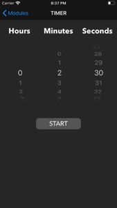
Once the user chooses the timer module, they are taken to a custom view that allows them to set, pause, resume, and cancel timers. The view looks as follows:

The time selector (known as a pickerview) is populated with possible timer options as follows:


 fileprivate func initPickerData() {
        var hours: [String] = []
        for hour in 0...23 {
            hours.append("\(hour)")
        }
        var minAndSec: [String] = []
        for min in 0...59 {
            minAndSec.append("\(min)")
        }
        pickerData.append(hours)
        pickerData.append(minAndSec)
        pickerData.append(minAndSec)
    }

// MARK:- UIPickerView
extension TimerModeViewController: UIPickerViewDataSource, UIPickerViewDelegate {
    
    func numberOfComponents(in pickerView: UIPickerView) -> Int {
        return pickerData.count
    }
    
    func pickerView(_ pickerView: UIPickerView, numberOfRowsInComponent component: Int) -> Int {
        return pickerData[component].count
    }
    
    func pickerView(_ pickerView: UIPickerView, attributedTitleForRow row: Int, forComponent component: Int) -> NSAttributedString? {
        let title = pickerData[component][row]
        return NSAttributedString(string: title, attributes: [NSAttributedString.Key.foregroundColor: UIColor.white])
    }

}
					

The user’s selections in the pickerview are stored in temporary variables for future use when the user selects start as follows:


    fileprivate var selectedHours = 0
    fileprivate var selectedMinutes = 0
    fileprivate var selectedSeconds = 0
    
    func pickerView(_ pickerView: UIPickerView, didSelectRow row: Int, inComponent component: Int) {
        switch component {
        case 0:
            selectedHours = Int(pickerData[component][row]) ?? 0
        case 1:
            selectedMinutes = Int(pickerData[component][row]) ?? 0
        case 2:
            selectedSeconds = Int(pickerData[component][row]) ?? 0
        default:
            print("Unexpected component selected.")
        }
    }
					

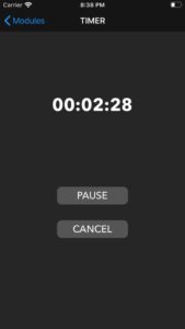
Once the user selects start, the view looks as follows:

When the user selects start, the pickerview is replaced with a text label that displays the time remaining on the timer. In addition, the start command is sent to the Arduino to be transmitted to the Big Board. First, the time, minutes, and seconds selected by the user must be converted to seconds and the start message must be created (“sXXe” where “XX” is the time the user selected in seconds). This is all done as follows:


    fileprivate func toSecondsFrom(hours: Int, minutes: Int, seconds: Int) -> Int {
        return seconds + (minutes * 60) + (hours * 60 * 60)
    }
    
    fileprivate func toHoursFrom(seconds: Int) -> Int {
        return seconds / 3600
    }
    
    fileprivate func toMinutesFrom(seconds: Int) -> Int {
        let hrsInSeconds = toHoursFrom(seconds: seconds) * 3600
        return (seconds - hrsInSeconds) / 60
    }
    
    fileprivate func toSecondsFrom(seconds: Int) -> Int {
        let hrsInSeconds = toHoursFrom(seconds: seconds) * 3600
        let minInSec = toMinutesFrom(seconds: seconds) * 60
        return seconds - hrsInSeconds - minInSec
    }
    
    fileprivate func startCommand(with seconds: Int) -> String {
        // From iOS App to Dev Board.
        // Format: s[0-9]+e
        // Format Description: ‘s’, then 1 or more digits, then ‘e’
        return "s\(seconds)e"
    }
    
    var delaySeconds = 1
    var delayTimer = Timer()
    
    func createDelayTimer(){
        delayTimer = Timer.scheduledTimer(timeInterval: 1, target: self, selector: #selector(TimerModeViewController.delay), userInfo: nil, repeats: true)
    }
    
    @objc func delay() {
        if delaySeconds == 0 {
            delayTimer.invalidate()
            delaySeconds = 1
            let hrs = String(format: "%02d", selectedHours)
            let min = String(format: "%02d", selectedMinutes)
            let sec = String(format: "%02d", selectedSeconds)
            timeLabel.text = "\(hrs):\(min):\(sec)"
            runTimer()
        } else {
            delaySeconds -= 1
        }
    }

    func runTimer() {
        clockTimer = Timer.scheduledTimer(timeInterval: 1, target: self, selector: #selector(TimerModeViewController.countdown), userInfo: nil, repeats: true)
    }
    
    @objc func countdown() {
        if seconds == 0 {
            clockTimer.invalidate()
            commandToSend = cancelCommand
            status = .notStarted
            
            // update UI
            timePickerView.isHidden = false
            timeLabel.isHidden = true
            startButton.setTitle("START", for: .normal)
            cancelButton.isHidden = true
        } else {
            seconds -= 1
            let hrs = String(format: "%02d", toHoursFrom(seconds: seconds))
            let min = String(format: "%02d", toMinutesFrom(seconds: seconds))
            let sec = String(format: "%02d", toSecondsFrom(seconds: seconds))
            timeLabel.text = "\(hrs):\(min):\(sec)"
        }
    }

@IBAction func onClickStart(_ sender: UIButton) {
        switch status {
        case .notStarted:
            // start timer
            let timerSeconds = toSecondsFrom(hours: selectedHours, minutes: selectedMinutes, seconds: selectedSeconds)
            commandToSend = startCommand(with: timerSeconds)
            status = .started
            
            // update UI
            timePickerView.isHidden = true
            timeLabel.isHidden = false
            cancelButton.isHidden = false
            startButton.setTitle("PAUSE", for: .normal)
            
            seconds = timerSeconds
            createDelayTimer()
            
            timeLabel.text = "Initializing Timer"
            break
            ...
 }
					

As seen above, the app maintains its own timer in case the status/finished commands are not received from the Big Board. Before starting this timer, a delay is added to allow for the start message to be sent and received.
Now that the timer is started, the app listens for status and finished messages and updates its UI accordingly as follows:


    fileprivate func parseCommand() {
        // removing invalid characters
        cache = cache.replacingOccurrences(of: "\n", with: "", options: NSString.CompareOptions.literal, range: nil)
        cache = cache.replacingOccurrences(of: "\r", with: "", options: NSString.CompareOptions.literal, range: nil)
        cache = cache.replacingOccurrences(of: "\t", with: "", options: NSString.CompareOptions.literal, range: nil)

        // first index of character that marks end of command
        var firstEnd = cache.firstIndex(of: "e")
        while firstEnd != nil {
            // getting next command
            let fullCommand = String(cache[...firstEnd!])
            let len = fullCommand.length

            // getting type of command
            let instruction = fullCommand[0]

            switch instruction {
            case "t":
                // status command received
                let timer = Int(fullCommand[1..<;len-1]) ?? 0
                let hrs = String(format: "%02d", toHoursFrom(seconds: timer))
                let min = String(format: "%02d", toMinutesFrom(seconds: timer))
                let sec = String(format: "%02d", toSecondsFrom(seconds: timer))

                // update timer
                timeLabel.text = "\(hrs):\(min):\(sec)"
            case "f":
                // finished command received
                timeLabel.text = "00:00:00"
                timeLabel.isHidden = true
                timePickerView.isHidden = false
                cancelButton.isHidden = true
                startButton.setTitle("START", for: .normal)
                status = .notStarted
            default:
                print("Unrecognized command received: \(fullCommand).")
            }

            // deleting command that has been already processed
            cache = cache.substring(fromIndex: len)

            // getting next index of character that marks end of command
            firstEnd = cache.firstIndex(of: "e")
        }
    }
					

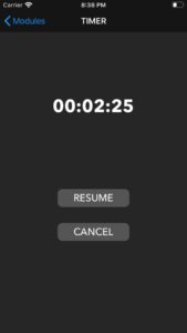
The user can pause the timer, which changes the view to look as follows:

Pauses are handled as followed:

    // MARK:- UIActions
    @IBAction func onClickStart(_ sender: UIButton) {
        switch status {
        ...
        case .started:
            // pause timer
            commandToSend = pauseCommand
            clockTimer.invalidate()
            status = .paused
            
            // update UI
            startButton.setTitle("RESUME", for: .normal)
            break
        ...
    }
    				

The user can then resume the timer, which is handled as follows:

					
    // MARK:- UIActions
    @IBAction func onClickStart(_ sender: UIButton) {
        switch status {
        ...
        case .paused:
            // resume timer
            commandToSend = resumeCommand
            runTimer()
            status = .started
            
            // update UI
            startButton.setTitle("PAUSE", for: .normal)
            break
        }
    }
    				

The user can cancel the timer at any time, which is handled as follows:


    // MARK:- UIActions    
    @IBAction func onClickCancel(_ sender: UIButton) {
        // cancel timer
        commandToSend = cancelCommand
        clockTimer.invalidate()
        status = .notStarted
        
        // update UI
        timePickerView.isHidden = false
        timeLabel.isHidden = true
        startButton.setTitle("START", for: .normal)
        cancelButton.isHidden = true
    }
    				

In regard to how Bluetooth is set up and how messages are sent and received, the full code can be seen in Appendix B. Ultimately, there is a lot of initialization that needs to be done, but once that is complete, there are several callbacks provided by Adafruit that can be used to send and receive messages.
Sending messages is done as follows:


    fileprivate func send(message: String) {
        print("send called with message: \(message)")
        guard let uartData = self.uartData as? UartPacketManager else { DLog("Error send with invalid uartData class"); return }
        
        if let blePeripheral = blePeripheral {      // Single peripheral mode
            uartData.send(blePeripheral: blePeripheral, text: message)
        } else {      // Multiple peripheral mode
            let peripherals = BleManager.shared.connectedPeripherals()
            
            if let multiUartSendToPeripheralId = multiUartSendToPeripheralId {
                // Send to single peripheral
                if let peripheral = peripherals.first(where: {$0.identifier == multiUartSendToPeripheralId}) {
                    uartData.send(blePeripheral: peripheral, text: message)
                }
            } else {
                // Send to all peripherals
                for peripheral in peripherals {
                    uartData.send(blePeripheral: peripheral, text: message)
                }
            }
        }
    }
    				

Receiving messages is done as follows:


// MARK: - UartPacketManagerDelegate
extension TimerModeViewController: UartPacketManagerDelegate {
    
    func onUartPacket(_ packet: UartPacket) {
        // Check that the view has been initialized before updating UI
        guard isViewLoaded && view.window != nil else { return }
        
        onUartPacketText(packet)
        self.enh_throttledReloadData() // it will call self.reloadData without overloading the main thread with calls
    }
    
    @objc func reloadData() {
        parseCommand()
    }
    
    fileprivate func onUartPacketText(_ packet: UartPacket) {
        guard packet.mode == .rx else { return }

        if let string = stringFromData(packet.data, useHexMode: Preferences.uartIsInHexMode) {
            cache += string
        }
    }
    
}
    				

In order for this to work, the connection must be established and set up be completed (again, refer to Appendix B for the set up since it is too lengthy and uninteresting to be included here).

RESULTS

We produced a functioning timer that could communicate with a smartphone application. The app could send a time to the PIC32, which would then count down that time and animate grains of sand that would drop periodically in accordance with the time remaining. When the PIC32 finished counting down, it would send a finish command back to the app. In the end, both the app and the PIC32 ran independent timers as not every timer update would reach the application. This resulted in the two timers being a little off (typically ± 2 seconds) however, this was more consistent than sending time updates. The grains of sand would drop based off of how much time was remaining and what the timer was set for. A maximum of 30 grains of sand would be animated. In the case that the timer was set for less than 30 seconds, then a number of grains equal to the amount of time in seconds would be animated. Here are videos of our timer in action:

Our project is seen as a fun addition to a kitchen or similar setting in which a timer may be needed. The user can set a timer from their device, and peek over at the hourglass as needed, which provides a clear and enjoyable indication of how much time is remaining. Our project is safe to use and can be utilized by all who are familiar with operating smartphone applications.
The PIC32 runs six total threads. Two of which are timers ( timer and hourglass ), two are used for serial connections ( serial and serial_aux ), and the remaining two are for animation and command interpretation. The six threads run concurrently, with the two timer threads yielding a majority of the time before updating values each second.
Our serial thread receives messages typically at a rate of 2 messages per second. Our project utilized two UART instances. One to send and receive data from the Arduino and another to display data on a serial port using PuTTy. This additional UART was used for testing if messages were being properly received and sent, as the messages could be displayed in a PuTTy terminal. Additionally, the Arduino Serial Monitor was used to see the status of messages being passed from the PIC32 to the Arduino, which would then be sent to the phone application.
As seen in the video, our system experiences a lot of flicker upon initialization. We believe this to be the result of both ball_init() and the animation thread running at the same time, as these are the only places where sand is drawn. We attempted to resolve this issue by adding conditions to the while loop that the animation thread runs in, but this did not correct the issue. Another issue was that we were unable to send consistent timer updates from the PIC32 to the smartphone application. We were unable to locate where exactly in the chain of connections this issue was, so we were unable to resolve it. As a workaround, both the app and PIC32 kept their own timers. Since there was a delay in the PIC32 starting, a “Timer Initializing” state was added to the smartphone application to get the timers to start at around the same time. When the phone timer ends, it will send a signal to the PIC32 to tell it to stop.
Another key error that we encountered was potential interference from other present devices. Our system is receiving messages constantly. If the application sends a start command, it will continue sending start commands until a new command is selected. This was done in case the PIC32 missed the first start command. One issue we encountered was that, on some occasions, one of the repeated start commands would not reach the PIC32. As a result, the next start command would be seen as a new command and the system would restart. Unfortunately, due to time constraints, we were unable to tackle this issue.
Overall, we were able to achieve the desired basic functionality of our system. The timer properly drops grain of sand, which follow similar physics rules to real sand. The app and PIC32 both run a timer for the desired amount of time and can properly start, resume, pause, cancel, and finish as desired.

CONCLUSIONS

Our project met our expectations for what we had hoped to accomplish. All of the basic and necessary functionality was present. There were additional features we had hoped to implement, but were cut due to time constraints and part issues. We did not intend to use an Arduino as an intermediary between the bluetooth and the PIC32, but needed to do to the complexity of our bluetooth part. We had also planned to use an LED matrix instead of the TFT display, but received a broken matrix and would not have been able to get a replacement by the deadline. Another intended feature was to use an accelerometer to allow users to rotate the hourglass and pause or reset it by placing it on its side or flipping it over respectively. This feature was cut due to ordering an incorrect part and not having the time to try and implement it. If we were to redo this project, we would use the Bluefruit LE UART Friend instead of the SPI version and try a different accelerometer. We would also try to use the small board to make the system less bulky and attempt to enclose it in a 3D printed frame so the system looks neater.
That said, we feel our design meets user expectations for an hourglass and timer app. The smartphone application is similar to other standard timer apps, which makes it easy for users to interface with. The hourglass periodically drops grains of sand, which is the expected behavior of an hourglass. Hourglasses are something most people are familiar with, so they could correctly interpret the dropping of sand as the passing of time, and when the sand runs out, the time will end.
Our project is based off of the “ Digital Hourglass Alarm Clock ” designed by students at the Potsdam University of Applied Sciences. While their design focuses more on the usage of an accelerometer and moving the hourglass, we focused on bluetooth and using a smartphone to set the timer.
Our project had few safety concerns, as the largest voltage present was a 5V signal from the Arduino which was lowered to a 3.3V signal to enter into the PIC32. With more time, we would do more to enclose the system and keep the wires hidden. This would help keep users from potentially removing wires or exposing themselves to small voltages.
In conclusion, our project met our expectations for a final design project. We felt that a significant focus of our project was based around the PIC32, which is the aim for this course. While not able to implement all the features that we wanted to, our group prioritized the most important features and succeeded in implementing them.

Source: VIRTUAL HOURGLASS TIMER

The post VIRTUAL HOURGLASS TIMER appeared first on PIC Microcontroller.

Countdown Timer using PIC16F84 microcontroller

$
0
0

It’s a kitchen timer. Use it to time spaghetti, or maybe an egg. It uses two PICs, one acts as a keyboard encoder, the other drives the display and supports the timer functions. You key in the desired time and press ‘#’. It’s accurate to 1/100th of a second, which can make all the difference I’m sure you’ll agree.

You can buy something similar to this from Denkimono.

Countdown Timer

Operation:

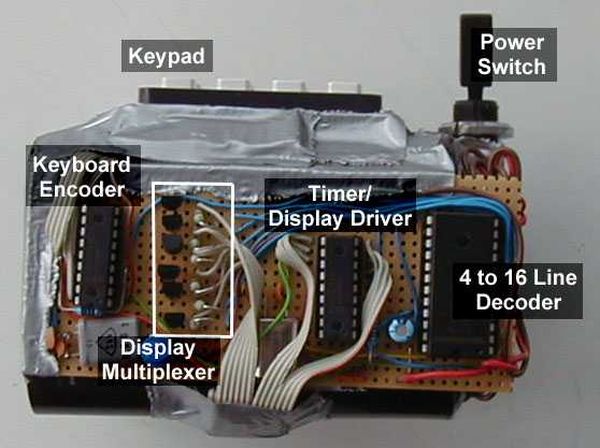
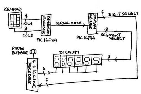
The PIC16F84 doesn’t have enough I/O lines to drive the display and keyboard so the keyboard encoding was done by one PIC and the display driving by another. The keyboard data was transferred to the display driver PIC over a single serial line. Even then there were not enough lines for the display driver PIC to drive the LED segments and select the display digit directly, so a 4 to 16 line decoder was used. This uses a 4-bit binary encoded input to select one of 16 outputs. This way the PIC was able to select each of six digits using only 4 output lines (3 to select the digit and 1 to latch the data to the decoder).

Schematic Countdown Timer

3 binary inputs decode to 8 outputs so one of the spare outputs was connected to the buzzer. The drawback with this is that the display and the buzzer cannot operate concurrently. This was turned into a ‘feature’ by flashing the display when the buzzer is sounding.


For more detail: Countdown Timer using PIC16F84 microcontroller

The post Countdown Timer using PIC16F84 microcontroller appeared first on PIC Microcontroller.

Simple RF/Microwave Frequency Counter using PIC16F876A

$
0
0

2. Counter

The whole counter design is based on the PIC micro-controller 16F876A. The latter includes several peripherals and just a few of them are used in this project. The most important in this project are two internal, hardware counters/timers called TMR0 and TMR1. The TMR0 timer generates very precise interrupts every 100 microseconds (10kHz) from the 20MHz clock/reference. All required timings for the counter timebase are simply integer multiples of this basic period.
Frequency Counter
The TMR1 is used as a 16-bit (binary) input-signal counter. Its maximum counting frequency is just around 16.7MHz. Therefore, the first four flip-flops of the input-signal-counter chain are added externally as 74Fxxx-logic devices. The first two stages use one of the fastest 74Fxxx-series devices, the 74F50109 dual J/K-flip-flop. Further, the 74F50109 is also specified as metastable-immune and is therefore the ideal component for the counter gate.

A more conventional 74F74 dual D-flip-flop is used in the third and fourth stages. The TTL flip-flops require pull-up resistors to drive the PIC ports RC0, RC1, RC2 and RC3. RC0 is used as a clock input to the TMR1 at the same time. Replacing the 74F74 with a 74ACT74 could save some current and two pull-up resistors. The 74F50109 has the same pin-out and logical function as the 74F109, but the latter has a lower frequency limit and is not specified metastable-free.

The typical frequency limit of the 74F50109 is specified 150MHz. Driving the 74F50109 with a fast switching transistor 2N3960 (ft=1.6GHz) and a schottky diode 1N5712 to prevent saturation, reliable counting can be achieved up to 190-200MHz! Unlike conventional AND or OR gates, the J/K gate minimizes the jitter of the counting result (wandering of the last digit) regardless of the input signal. Since the /K input of the 74F50109 is inverted, two port pins (RA2 and RA3) of the PIC are required to drive the J and /K inputs with minimal skew.

On the other end, the counter needs to be extended beyond the 4 bits of the 74Fxxx logic and 16 bits of the TMR1 adding up to 20 bits of resolution. To avoid disrupting the operation of the main 100us timer, the TMR1 is not allowed to generate interrupts. The TMR1 overflow (interrupt) flag is checked during every 100us (TMR0)interrupt. The overflows are counted in two additional 8-bit registers. The overall counter resolution is therefore 36 bits.

These 36 bits are truncated to 32 bits, the upper 4 bits are not used. 32 bits allow counting beyond 400MHz with a resolution of 0.1Hz (gate time 10s). None of these counters is ever being reset! The counter value at the beginning of the measurement is stored and subtracted from the end value. Finally, the 32-bit binary result is converted to a 10-digit decimal number and the latter is displayed with the leading zeros blanked, decimal point and units (MHz or kHz).

The basic counter software allows three resolutions (selected with RC4 and RC5): 10Hz, 1Hz and 0.1Hz in direct counting mode (no prescaler), corresponding to gate times of 100ms, 1s and 10s. When used with a divide-by-64 prescaler, the three available resolutions become 1kHz, 100Hz and 10Hz, corresponding to gate times of 64ms, 640ms and 6.4s. All these gate times are obtained by counting the 100us (10kHz TMR0) interrupts.
Schematic Frequency Counter
The PIC 16F876A drives a standard LCD module with a HD44780 controller and a resolution of two rows of 16 characters each. The HD44780 requires 8 data lines (port B of the 16F876A) and three control signals: RegisterSelect (RC6), Read/Write (GND) and Enable (RC7). Since the data presented on the 8-bit-wide output port RB0-7 is only written to the HD44780, the R/W input is hardwired to ground (/Write). The LCD back-light LEDs are supplied through two 10ohm current-limiting resistors.


For more detail: Simple RF/Microwave Frequency Counter using PIC16F876A

The post Simple RF/Microwave Frequency Counter using PIC16F876A appeared first on PIC Microcontroller.

IK3OIL 16F84 PIC Frequency Counter Files

$
0
0

Caption (copied from the NorCal meeting listed in the links below):

IK3OIL Frequency counter built by Wayne McFee.  This is from IK3OIL’s web site, and the cost of the counter was about $2, minus the display, which was about $7.  Wayne got the source was www.shopeio.com.  They are located in Gardenia, California.
PIC Frequency Counter
Design and Code by Francisco IK3OIL

This frequency counter was mentioned on the QRP-L mailing list.
I offered to put up some more information on the counter on this web page.
I have not built one (yet) nor do I have any further information than what is here.

UPDATE!: I did build a counter it was not an IK3OIL counter but based on comments by PIC Elmer WB8RCR on Echolink, I built instead an OM3CPH counter.
It works FB! Thanks for the hints and the great work with the PIC Elmer course John!

Davewb4 at aol.com    provided these files

Here are some comments he made to the QRP-L list:

HI All: Wayne got the hex code for the counter  from me. I got it from 
Francisco (IK3OIL). I have built 5 of these counters and  all work from the git-go. 
I have the hex code and can supply it to anyone who  wants it. I also have 
redone the art work for Francisco's board. He used some NO  tactile switches that 
are hard to find so I changed the board slightly. I will  be happy to supply 
that to any one who wants it. The counter costs about $ 10 to  build since you 
can get the PIC16F84 chip from Micro-Chip as samples. If you are  going to 
Orlando this week end for the ham fest I will be there at the ARCI  meeting with 
a IK3IOL micro counter and some Unicounters and a 2N2/20. IF anyone  wants to 
build a Microcounter but cannot program a chip, just send me an 18pin  Dip 
16F84 and I will be happy to program one for you. I also have the schematic  for 
the Micro-counter.
73
Dave Rogers
WB4CHK
Plantation, FL

---

www.eio.com/lcdprodt.htm

Here is a good  place to purchase the LCD. Click on character LCD and in the 
middle of the page  find Seiko L1671BIP...... A 1x16 character LCD, its back 
lit and the $ 6.00  price is nice. 

I must say I am overwhelmed by the interest
73
Dave

---

Since there is so much interest in this project,  here is what you get.

1. A very nice stand alone frequency counter for  the bench or
2. A digital readout for any rig. With the mode switch you can  set the IF 
offset to any of three combinations i.e.: VFO+IF.... VFO-IF or  IF-VFO
3. With some additions it can count into the Gig region. It has a  pre-scaler 
option. ( Wayne McFee NB6M has some mods for that, so if you are  interested 
in counting that high you should contact him. I use them for rigs I  build.  I 
installed one in my 2N2/20. It has an 11meg IF & a 3meg VFO  so I use VFO+IF 
to read 14MHZ
4. A typical 14mhz count would be  14.060.45
If you use my art work for the PC board, please note I use MS paint  and 
everything is oversize. I suggest first of course, reverse the design then  print 
a copy of the board. Place an 18pin dip socket on the print and compare  the 
hole line up. It will probably be to large. I then use the size program on  my 
HP laser jet program to reduce the size. Try 74% that should be close. Once  
you get the Dip to exactly the correct size all the rest will be OK. I use PnP  
blue to make the boards. If you want to build the counter and do not have a  
programmer for the PIC16F84, just send me one and I will program it for you. 
Any  questions just ring. I also have some pictures of the completed board, the 
 switch change, the LCD connections and the finished counter. It's a large 
file  3.5MB.
73
Dave  


Here is the link to the PDF file by IK3OIL:
http://digilander.libero.it/ik3oil/_private/Frequenzimetro_eng_2003.pdf

Here is a link to the AN592 MicroChip Application note referenced in
Francesco’s Frequency Counter above:
http://ww1.microchip.com/downloads/en/AppNotes/00592d.pdf

Here is a link to the NorCal meeting where the counter was mentioned:
http://www.norcalqrp.org/mtg2005_02.htm

Here is a copy of the PIC source code that I got from Dave ( Davewb4  at aol.com )
ik3oilcounter.hex

Here are the layout/schematic files compressed into a zip file
layout.zip

NOTE: Daveb4 at aol.com has agreed to be a contact person re this counter as I know nothing more
than what is here.
—–

Here is a note from ve7wrs re a similar PIC Counter project

 All,

You might also want to check-out the frequency counter that Phil Rice,
VK3BHR,  in Australia produced. It is an almost identical design; PIC 16F84
with a single input transistor. In fact he gives credit to IK3OIL for
inspiring the design.
http://ironbark.bendigo.latrobe.edu.au/~rice/

Phil even makes the source code available if you want to tweak it. On the
web site click on the Updated Frequency Counter. I haven't built it, but I
did email Phil for ideas about using a TCXO instead of the 4 Mhz crystal. He
was very helpful.

Phil also has a PIC16F84  L/C meter project which I did build. It functions
very much like the Almost all Digital meter (which I don't own).  Mine works
great, and is really useful for sorting out unmarked or illegible inductors
and capacitors. Highly recommended.

-Walter
VE7WRS


-----

Here are some photos from Dave for the ik3oil counter

Here are some photos from Dave for the ik3oil counter

K3OIL Micro-counter mounted in a K8IQY  2N2/20
Mounted in a 2N2/20 with the PC board separate from the LCD and connected by a 16 pin cable

LCD and connected by a 16 pin cable

Source: IK3OIL 16F84 PIC Frequency Counter Files

The post IK3OIL 16F84 PIC Frequency Counter Files appeared first on PIC Microcontroller.

2.5 GHz Frequency counter using PIC16F870

$
0
0

Background
It is time to update the frequency counter again.
A frequency counter is one of the most important measuring tool we need as homebrewers of RF electronic.
This frequency counter has very high performance and still is very easy to build and to use. Anyone can build it and have fun.
The counter is based around 6 LED displays which will present the frequency with 1kHz resolution.

pick-up coil
I don’t find it necessary to have more digits.
The frequency will be presented on the LED display and at the same time also sent on the RS232 line.
If you want you can connect the counter to a computer and display the frequency information there.
In that case you don’t need any LED displays. This frequency counter is very sensitive and need just a few millivolt of RF to measure the frequency. You can easy connect it to any oscillator or you can make a pic-up coil to probe the oscillator. (More about this later)
To make this counter even more useful and intelligent, I have added an option for offsetting the frequency showed on the LED display with 2 jumpers SW1 and SW2. The offset calculation is easy activated with 2 jumpers, one for 455 kHz and one for 10.7 MHz.

It works like this:
Imagine you have a radio receiver and you wish to display the receiving frequency. As you know the oscillator in a radio receiver works 455 kHz or 10.7 MHz above the receiving frequency. The 455 kHz and 10.7 MHz difference is called IF (Intermediate Frequency).
So to display correct frequency, the counter needs to subtract the incoming frequency with 455 kHz or 10.7 MHz depending on your receiver system. 455 kHz is used in (narrow) band units and AM reception. 10.7 MHz is used in WB (wide band) and commercial receivers.

Example:
You have a radio and you want to listen at 100.0 MHz (the IF is 10.7 MHz) The oscillator will be oscillating 10.7 MHz above the 100 MHz, so the oscillator is at 110.7 MHz. If you would measure the frequency with an ordinary counter you would get 110.7 MHz on the LED display but, by activating the offsetting function this counter will subtract and display 100.0 MHz. The offset calculation is easy activated with 2 switches, one for 455 kHz and one for 10.7 MHz.
Boy, I wish I had this counter when I was building my first receiver for aircraft-band, which was manually tuned and not very stable.

Hardware and schematic

Most HF frequency counters need a prescaler in front of the counter unit.
In this case I use a circuit called LMX2322 which has prescaler function.
Of course you can use any prescaler as long as it divides by 64.
I have chosen this circuit since I have them and they are very sensitive and easy to work with.
The sensitivity is so good that in many cases you will need a attenuator based on a few resistors to make it work properly. More details later.
The prescaler has two differential inputs called Fin and /Fin.
If you wish you can connect /Fin to ground and use only Fin going to pin 8. Two 100 resistor forms 50ohm for impedance input matching.

The output of the prescaler (CPo) is a TLL lever where the frequency is divided by 64.
The signal then enters the microcontroller into its counting register (RC0). The microcontroller count the input pulses during 64mS.
The accuracy of this counter is set by the frequency of the 13MHz crystal.

The crystal frequency can be fine tuned by a variable capacitor C11 to obtain very high accuracy.
The frequency is displayed on the 6 LED display in multiplexed way. It means that only one LED is turned on at the same time.
First LED 1 is lightning, then LED 2 and so one. This goes so fast that it appears that all are lightning. During the 64mS counting, the LEDs are off to decrease noise on the power line. When the display are updated the info is also sent on the RS232 line (RC6).
A PNP transistor convert the TTL voltage to RS232 voltage. The connector is a standard 9-pol female dsub which will fit into any computers comport. If you are not going to use this part you don’t have to build it.

Frequency offset by SW1 and SW2.
When SW1 and SW2 is not activated the counter show actual frequency.
When SW1 is activated (short circuit) the counter subtract the measured frequency with 455 KHz.
When SW2 is activated (short circuit) the counter subtract the measured frequency with 10.7 MHz.

PCB

fq232.pdf PCB file for 1GHz frequency counter (pdf).

Frequency offset by SW1 and SW2

Above you can download a (pdf) filer which is the black PCB.
Above you will find two pic showing the assembly of all components on the same board.
The scale of the pdf is 1:1 and the two picture are magnified 4 times.
This is how the real board should look when you are going to solder the components.
It is a board made for hole mounted components and at the bottom layer you will have some surface mounted components.
Grey area is cuppar and each component is draw in different colours all to make it easy to identify for you.
Click on the two picw to enlarge them.

Sensitivity of input signal
Table below show my measurements of the sensitivity of this unit.
I have not measured below 60MHz and the upper limit is 220MHz since my generator ends there.
This counter should be able to measure up to 2.5 GHz easy.
The input signal is terminated at the prescaler with 50 ohm (2 x 100 ohm resistor parallell)
This is to match impedances and to give dBm measurements.

Frequency (MHz)
mV rms
uW (into 50 ohm)
dBm (into 50 ohm)
60
90
160
-8.0
80
60
69
-11.6
100
48
46
-13.3
120
40
32
-15.0
140
33
22
-16.6
160
27
15
-18.2
180
24
12
-19.2
200
24
12
-19.2
220
24
12
-19.2


Attenuator
Attenuator is some resistor to lower the input power and still obtain matching impedance.
It is very simple to build and works really good.
The picture at right show you how to build it and how to calculate damping.
You can serial connect several attenuators if you need to.

This attenuator damp 6dB.
6dB means that tge output power is only 1/4 of the input power.
It also means that the output voltage is 1/2 of the input voltage.
As you see I have used 100ohm resistor becasue I use SMD and they are cheap and accurate.

Windows software

Windows software

Download windows software
fq.zip (1.41Mb)
Click here to go to the software download page!


Unzip it and run setup, that is all. Just install the program and connect the cable to the frequency counter.
Make sure you set right comport in the software (Com1 or Com2).
If you want to make your own software you should know that the baud rate of the transmission is 1200 baud, 8 bit, 1 stop and no parity.

The PIC send data like this:
If the frequency is 128.250MHz the string will be : 01h, 02h, 08h, 2eh, 02h, 05h, 00h

Download PIC16F870 programs (INHX8M format)
The zip file contains hex file made for this project.

led_counter.zip Software 999MHz with 1kHz resolution (the hex files are zipped!)
led_counter_uhf.zip Software 2.5 GHz with 10kHz resolution(the hex files are zipped!)


Component support
This project has be constructed to use standard (and easy to find) components.
You can find all necessary components at my component page.

Final word
This part describes the construction of a very powerful frequency counting tool.
I hope you will have lot of use of your counter.
Do please send a photo of your construction and I put it onto the coming gallery.

You can always mail me if there is anything unclear.
I wish you good luck with your projects and thanks for visit my page.

Photo Gallery
Some assembled counters people has mailed me. Please mail me more.

Photo Gallery

Source: 2.5 GHz Frequency counter using PIC16F870

The post 2.5 GHz Frequency counter using PIC16F870 appeared first on PIC Microcontroller.


Internal Oscillator Recalibration Utility for PIC12F629

$
0
0

Description

The PIC 12F629 and 12F675 devices have an internal 4Mhz oscillator that enables the devices to be used without an external crystal or RC network.  This frees up one or two pins for I/O use and allows the device to be built into minimum component count designs.

The internal oscillator needs to be calibrated and this is achieved by reading a factory programmed calibration setting and writing it into the OSCCAL register during initialisation of the device by the application software.

Internal Oscillator Recalibration

The calibration word is located at the last address in the user program memory area, address 0x3FF.  It is in the form of a RETLW instruction and the user code should include a CALL 0x3FF instruction which will return with the calibration setting in the W register. This can then be written into the OSSCAL register.

Problems arise if by accident or otherwise, the program memory at address 0x3FF is erased or over written.  Since the calibration value is unique to each individual PIC there is no way to know what it was, but it is possible to recover it by recalibrating against a known frequency.

That’s where this software and circuit come into their own.  Load a PIC with the code on this page and drop it into the circuit described here and within a couple of seconds it will provide a new calibration value to ensure the internal oscillator runs within 1% of 4Mhz.

PICkit 2 update

If you have a PICkit 2 programmer, get version 2.50 (or later) software from the Microchip website.  This includes a menu option to recalibrate and reprogram the OSSCAL setting in one operation.  This project page remains here for those who don’t have access to a PICkit2.

How it works

In order to calibrate the internal oscillator a known reference frequency is needed. Fortunately we don’t need signal generators or calibrated test equipment for this. In fact an accurate reference is available from the AC utility electric supply.  In most parts of the World the utility electricity supply is generated at a frequency of either 50 or 60Hz (many digital clocks take advantage of this fact to keep time)

Using almost any transformer (or Wall Wart) with a 6 to 12 volt RMS AC output we can obtain an accurate reference source to calibrate the PICs oscillator against.

Schematics, Construction, and Code

So let’s get on with it.  Construct the circuit shown below using a piece of strip or pad board, or just hook it up on a solderless breadboard.


For more detail: Internal Oscillator Recalibration Utility for PIC12F629

The post Internal Oscillator Recalibration Utility for PIC12F629 appeared first on PIC Microcontroller.

Digital alarm clock using PIC16F877 microcontroller

$
0
0

This is an alarm clock I built. It was very effective during the sort time I used it, because I programmed it to play a very annoying tune through a speaker. I actually started to wake up before the alarm went of, so other people in the house didn’t wake up from the annoying pitches it played.

Digital alarm clock

The JAL source code is available on my download page

Features

  • Timekeeping using the PIC’s timer0 interrupt
  • 4×20 hd44780 compatible backlit LCD, displaying the time in big numbers (4×4 and 4×3) * Alarm sound tune using PWM
  • computer interface for synchronizing time with the web.
  • (maybe battery backup (in case of a power outage…))

Status

Timekeeping: Rewritten in assembler. (losing one stack level, previously losing two stack levels, ISR and procedure time…) :Display: Done. Use’s Vasile’s 4-line lcd routines and tables to store the texts.
Bignumbers: Done. Data stored in tables.
Backlight: The backlight is dimmed using the internal CCP1 module of the PIC in PWM mode. :Input: Four pushbuttons on port D, handled by buttons.jal (function keypress(byte in key) return bit).
Alarm sound: Uses CCP2 in PWM mode, inspired by Vasile!
Menu code: Works. Can set time/alarm.
Computer link: (interface code) Nothing yet.

For more detail: Digital alarm clock using PIC16F877 microcontroller

The post Digital alarm clock using PIC16F877 microcontroller appeared first on PIC Microcontroller.

Programmable digital timer switch using a PIC16F628A

$
0
0

Digital timer switches are used to control the operation of electrical devices based on a programmed schedule. This project describes a programmable digital timer based on a PIC16F628A microcontroller that can be programmed to schedule the on and off operation of an electrical appliance. The appliance is controlled through a relay switch. This timer switch allows you to set both on and off time. That means, you can program when do you want to turn the device on and for how long you want it to be remained on. The maximum time interval that you can set for on and off operation is 99 hours and 59 minutes. The project uses a 16×2 character LCD with 4 push buttons to interact with the user.

digital timer

Circuit Design

The circuit diagram of this project is shown below. A 5 V relay is driven by a PN2222 transistor that is controlled by RB3 pin of PIC16F628A. Digital inputs from the 4 push buttons are read through port pins RA2, RA3, RA4, and RB0. The functions of these push buttons are discussed in the operation section below. A standard 16×2 character LCD is used in the project to display the the device status, program menu and time. The LCD is operated in 4-bit mode, therefore, only 6 I/O pins of PIC16F628A are required to drive it. A piezoelectric buzzer provides audible tone when the timer is started and stopped. It also beeps when the device is turned on or off. The + 5V power supply for the circuit is derived from a LM7805 regulator IC. The input to the regulator is given from a 9V DC wall adapter.

In the circuit diagram, the pins 15 and 16 of the LCD are shown open. These pins are available only in those LCDs that have a back light illumination LED. The pins 15 and 16 are the anode and the cathode of the LED. If your LCD has the back light LED, you can connect these pins to the power supply terminals with a 39 Ω resistor in series. The backlight LED enhances the readability of the LCD display in low illumination condition.

The complete circuit soldered on a general purpose prototyping circuit board is shown below.


For more detail: Programmable digital timer switch using a PIC16F628A

The post Programmable digital timer switch using a PIC16F628A appeared first on PIC Microcontroller.

2 Digit up/down Counter using PIC16F628A

$
0
0

This project comes via two circuits on 2 boards. The first circuit is designed around a PIC16F628A. It has been presented on an experimental PC board using surface-mount components and was built in less than 1 hour, with about 2 hours to write and finalise the program. See  P1 P2
The second circuit uses a PIC12F629 to produce a 2-Digit Up/Down Counter (see P3).
Both use “In Circuit Programming” via PICkit-2.
P5
Describes the up/down counter displaying the “gear” for motorcycles and racing cars.

2 Digit up or down COUNTER

The project shows what can be done with a micro and you can modify it to set an alarm at any count-value or set a limit such as “count-to-60.” You can add a buzzer or relay or increase the display to 3 digits. You need to remember that each additional display will reduce the illumination of each digit as they are “multiplexed (time-sharing).”

The experimenter PC Board shows the five “In Circuit Programming” pins and a diode on the positive rail to drop the 6v supply to 5.4v. The board also has a 100n surface mount capacitor and two surface-mount transistors. The Up/Down buttons have 22k resistors. TESTING THE CIRCUIT
Check the circuit by removing the chip and taking pins 6 and 18 to the 5v rail
ad make sure segment “A” illuminates. Do the same for all the other segments.
The circuit diagram does not have any voltages marked on it as the circuit is DIGITAL.
All the “lines” or “wires” or pins of a microcontroller will have rail voltage (5v) on them when they are HIGH and when you come to a resistor, the resistor will drop a certain voltage. The voltage it will drop will be the difference between rail voltage and the voltage developed across the component it is driving. If it is driving a LED, the LED will drop a characteristic voltage of between 1.7v and 3.6v, depending on the colour.
If the component is a transistor, the voltage developed between the base and emitter will be about 0.7v.


For more detail: 2 Digit up/down Counter using PIC16F628A

The post 2 Digit up/down Counter using PIC16F628A appeared first on PIC Microcontroller.

Propeller Clock Mechanically Scanned LED Clock using PIC16C84

$
0
0

This is the first clock I ever built. I’ve built a few LED signs, but they get boring because I already know the message.

How this clock works:
A motor spins the “propeller”, and a small microprocessor keeps track of time and changes the pattern on seven LEDs with exact timing to simulate a 7 by 30 array of LEDs. It is an illusion, but it works nicely.

Propeller Clock

If you want to build this clock, you will need a few things, including:
Skill with motors and mechanical things.
Prior electronic experience.
A dead VCR or floppy drive or other source of a suitable motor and miscellaneous parts.
A programmer that will program a PIC16C84 or 16F84 microprocessor.

I have provided (almost)everything else:
The Next Page with drawings and plans.

Download:
mclock.txt A full description how to build it.
mclkpart.txt The parts list.
mclock8.asm The source code in Microchip MPASM format.
mclock8.hex The hex code ready to load into a PIC16C84 or 16F84 chip.
mclksch2.gif A large and very readable schematic diagram.
mclkmoto.gif A drawing of the modifications to the motor.

If you can’t get that kind of motor, you can use the motor from an old disk drive. This page has a lot of pictures and will take some time to load. If you use a disk drive motor or any other DC motor with brushes 180 degrees apart, you’ll need the slightly revised code:
Download:
mclockt3.asm The source code.
mclockt3.hex The hex code ready to put in a chip.

If you don’t have any way to put the program into a PIC 16C84 or 16F84 chip, you can build your own programmer.

Printed Circuit Board Layout for a version of the clock.

License:
The hardware design and software are covered under the GNU General Public License.


For more detail: Propeller Clock Mechanically Scanned LED Clock using PIC16C84

The post Propeller Clock Mechanically Scanned LED Clock using PIC16C84 appeared first on PIC Microcontroller.

Gear Clock using PIC16F676 Microcontroller

$
0
0

I can’t take credit for the design of this one.  I bought the
gear as a clock a few years ago.  It was mounted on a frame
and had one of those cheap clock units running it.  The
gear is designed to be driven by the minute-hand shaft of
the clock mechanism.

Gear Clock

The problem was that it kept breaking.  I think the problem
was that the clock mechanism wasn’t strong enough to hold
the weight of the gear.

I bought a stepper motor with four input wires.  A PIC
16F676 microcontroller functions as the timer.  Every
three minutes, four output pins are driven either high
or low for half a second.  These are each connected to
a pair of transistors – one PNP, one NPN to drive the
motor with more current.  The stepper motor rotates 18
degrees each time.


For more detail: Gear Clock using PIC16F676 Microcontroller

The post Gear Clock using PIC16F676 Microcontroller appeared first on PIC Microcontroller.

Build a digital clock with its digits levitating in the air using PIC16F84

$
0
0

Red digits on this photo appear to float in the air in front of the clock. This illusion is based on inertia of a human eye. If LED-formed digits will periodically and frequently enough flash, they will appear solid and steady. And since the matrix of digits is formed by a mechanically scanned single line of LEDs, and the fast rotating clock body is not visible, it leaves digits “suspended” in the air. The first clock using this concept was built (and PIC microcontroller code written) by Bob Blick, please visit his page for yet more photos of his original clock and clocks built by other people.

digital clock

The heart of this clock is PIC16F84 microcontroller. (Older PIC16C84 version works just fine). The microcontroller is programmed with the code provided below. If you don’t have a PIC programmer, it isn’t difficult to make one. A few parts (for a couple bucks) connected to the parallel port of your PC will program the PIC for you.

First, mechanical stuff. We will use a 12V automotive fan (sells for $12.95) as a kit, containing almost all nesessary mechanical parts. The only extra part you’ll need is a ball bearing and brass tube about 2mm in diameter. The bearing I’ve used was 22mm ext. dia., 10mm int. dia., and 6mm high. This size is not very critical, (that’s just what I had in hand) but try to find something close: this one fits very nicely.

First you’ll need to take the fan apart. The front grill and swing action mechanism parts aren’t needed.  Don’t throw away the  propeller yet, you will use it’s hub later.

schematic digital clock

Next step is disassembling the motor. Slide the windings and commutator along the shaft toward non-threaded end of the shaft leaving about 15mm of the shaft at this end. Be careful not to separate the commutator from the rotor windings. The easiest way to do this is to stick the commutator end of the shaft to the rear sleeve bearing (white plastic part) and just tap the shaft with a hammer to the other end, using sleeve bearing as a support. Once it’s done, you’ll need to solder a wire to the ends of three commutator segments: 2 wires to any adjacent segments, and one wire to the segment opposite the other two chosen previously.


For more detail: Build a digital clock with its digits levitating in the air using PIC16F84

The post Build a digital clock with its digits levitating in the air using PIC16F84 appeared first on PIC Microcontroller.


4-digit Up/Down counter with preset, reset, hold and overflow output using PIC16F88

$
0
0

Overview

A four digit decimal counter for the PIC 16F88 with the following features:

  • Count up / down
  • Reset
  • Free running or hold on count over/underflow
  • User count preset
  • Over/underflow output

Description

This is a 4 digit decimal counter which can operate as a free running counter or in count and hold mode with manual reset.  In either mode the counter can be preset to count to a specified value.  Clock edge and leading zero suppression can also be configured.

The 7-segment display and indicator LEDs are multiplexed.  It will drive most common anode 7 segment LEDs.  I used four single digit LEDs but a four digit LED module could also be used.

In free running mode the overflow output resets on the next clock pulse. Therefore the pulse duration is directly related to the input clock frequency. 

The clock input goes to a Schmitt trigger input pin on the PIC.  It will accept a 0-5V input signal only.  If it’s used with a mechanical switch you should use the debounce circuit shown on the schematic.

I’ve had the circuit clock reliably at 200Hz and it should be able to operate without missing a clock pulse at frequencies up to 5Khz.

4-digit Up,Down counter

Operation

The counter can be configured for either a rising or falling clock edge and leading zero suppression.  Once applied these settings are stored in NVRAM and retained across a power cycle.  To enter config mode, hold down the ‘set’ switch at power-on.

The counter normally runs from 0000 to 9999.

It can be configured to count up to, or down from a preset number using the set and adjust keys.

The preset number is used until it is manually changed.  When it has been changed the preset is saved to EEPROM and will be restored at power on.

Overflow:-
Active when count reaches preset value

Count Hold:-
On – Counter in Hold mode
Off – Counter in free running mode

Count Up / Count Down :-
indicates the count direction

For more detail: 4-digit Up/Down counter with preset, reset, hold and overflow output using PIC16F88

The post 4-digit Up/Down counter with preset, reset, hold and overflow output using PIC16F88 appeared first on PIC Microcontroller.

PIC Microcontroller timer Video Project

PIC16F877 up down counter code and Proteus simulation

$
0
0

This PIC16F877 microcontroller tutorial answers the question,
” How to implement a up down counter using PIC16F877 ? ”


Using PIC16 simulator (Proteus) you can verify this counter code and change it according to your needs. Using one push button (Labeled as Count, as shown in figure below) you can increment (When SW1 switch is towards up position) or decrement (When SW1 switch is towards down position) count value (displayed on LCD) as you desire. This code is written in C language using MPLAB with HI-TECH C compiler. You can download this code from the ‘Downloads‘ section at the bottom of this page.

In this article, it is assumed that you know, how to interface LCD with PIC16F877 microcontroller. If you don’t then please read this page.

The following diagram (made in Proteus) shows the PIC microcontroller circuit diagram.

PIC16F877 up down counter code and Proteus simulation Schematic

The above figure was taken after setting time to 03:59:38, timer0 is used as the base for digital clock generation. Timer0 is used here to generate 1msec interrupts. After every 1msec a global variable named msCounter increments. When msCounter reaches a value of 1000 then another global variable named secCounter increments and this process repeats itself. Similarly, when secCounter reaches 60, then  minCounter increments. And when minCounter reaches 60 then hrCounter increments. This process continues until hrCounter reaches 24 then all of these variables reset their values. LCD is updated with the new values of hrCounterminCounter and secCounter after every second.

You can set time using three push buttons attached on RE0RE1 and RE2 pins (As shown in the above figure). By pressing ‘Set Time‘ button one time, code enters in configuration state. Hours value starts to blink and you can modify it using Up and Down buttons. Pressing Up button increments the value and pressing Down button decrements the value. When you are done setting Hours value, press ‘Set Time‘ button again, then Minutes value will start to blink and you can adjust this value using Up and Down buttons. Similarly, after setting Minutes value, you can press ‘Set Time‘ button again, then Seconds value will start to blink and you can adjust this value using Up and Down buttons. When you are done adjusting the time, then press ‘Set Time‘ button for the last time and this clock will start to work normally.

A crystal of 4MHz value is used in this circuit, which makes this PIC16F877A run at a speed of 1MIPS (Million of instructions per second).

Code

The main function code is shown below.

Figure 2.   Main function code for digital clock on PIC16F877A

In the main function, firstly PORTE pins are made input and ADC is turned off on these pins. Then LCD is initialized using InitLCD() function. Then Timer0 is initialized to generate 1msec interrupts.

After that, in the while(1) loop, there is a state machine running. A variable named State is used to keep track of the current state of the clock. When this code starts, then State has a value of NORMAL_STATE. In the normal state, clock value is incremented after every second and whenever msCounter reaches a value of zero[1], then new values of hrCounterminCounter and secCounter are updated on the LCD. UpdateTimeCounters() function is called every time and it corrects the values of every counter variable depending upon the value of msCounter, which is incremented in the ISR function of timer0.

In the normal state, code keeps checking RE0 pin value, if ‘Set Time‘ button is pressed then RE0 pin value becomes zero. This is detected using if(!RE0) statement in the code. When ‘Set Time‘ button is pressed then state is changed to ‘CONFIG_HR_STATE‘ (i-e configure hours value state). In this state, Up and Down buttons are constantly monitored and hrCounter value can be adjusted. Similarly, by pressing ‘Set Time’ button again, state is changed to ‘CONFIG_MIN_STATE‘ (i-e configure minutes value state). In this state minCounter value can be adjusted using Up and Down buttons and by pressing ‘Set Time‘ button again, state is changed to ‘CONFIG_SEC_STATE‘ (i-e configure seconds value state). In this state secCounter value can be adjusted using Up and Down buttons. By pressing ‘Set Time‘ button again, state is changed to ‘NORMAL_STATE‘ and clock starts to run normally.


Source : PIC16F877 up down counter code and Proteus simulation

The post PIC16F877 up down counter code and Proteus simulation appeared first on PIC Microcontroller.

PIC16F877 stop watch code and Proteus simulation

$
0
0

This PIC16F877 microcontroller tutorial answers the question,
” How to implement a stop watch using PIC16F877 ? ”

PIC16F877 stop watch

Using PIC16 simulator (Proteus) you can verify this stop watch code and change it according to your needs. Using three push buttons (As shown in figure below) you can adjust time as you desire. Then after setting the time, value displayed on the LCD starts to decrease with each second and when this value reaches zero, then LED D1 is turned on. This code is written in C language using MPLAB with HI-TECH C compiler. You can download this code from the ‘Downloads‘ section at the bottom of this page.

In this article, it is assumed that you know,

  • How to make a simple digital clock using PIC16F877. If you don’t then please read this page.
  • How to interface LCD with PIC16F877 microcontroller. If you don’t then please read this page.
  • How to configure timer0 of PIC16F877 microcontroller.  If you don’t then please read this page.

The following diagram (made in Proteus) shows the PIC microcontroller circuit diagram.

The above figure was taken when time was 00:00:07, i-e only 7 seconds were remaining until LED D1 is turned on. Timer0 is used as the base for digital clock generation. Timer0 is used here to generate 1msec interrupts. After every 1msec a global variable named msCounter increments. When msCounter reaches a value of 1000 then another global variable named secCounter decrements and this process repeats itself. Similarly, when secCounter reaches 0, then  minCounter decrements. And when minCounter reaches 0 then hrCounter decrements. This process continues until hrCounter reaches 0. LCD is updated with the new values of hrCounterminCounter and secCounter after every second.

PIC16F877 stop watch Schematic

You can set time using three push buttons attached on RE0, RE1 and RE2 pins (As shown in the above figure). By pressing ‘Set Time‘ button one time, code enters in configuration state. Hours value starts to blink and you can modify it using Up and Down buttons. Pressing Up button increments the value and pressing Down button decrements the value. When you are done setting Hours value, press ‘Set Time‘ button again, then Minutes value will start to blink and you can adjust this value using Up and Down buttons. Similarly, after setting Minutes value, you can press ‘Set Time‘ button again, then Seconds value will start to blink and you can adjust this value using Up and Down buttons. When you are done adjusting the time, then press ‘Set Time‘ button for the last time and this stop watch will start to work normally.

Code

The main function code is shown below.

Downloads

Stop watch clock display code using PIC16F877 was compiled in MPLAB v8.85 with HI-TECH C v9.83 compiler and simulation was made in Proteus v7.10. To download code and Proteus simulation click here.


For more detail: PIC16F877 stop watch code and Proteus simulation

The post PIC16F877 stop watch code and Proteus simulation appeared first on PIC Microcontroller.

PIC16F877 based digital clock using LCD display (Code+Proteus simulation)

$
0
0

This PIC16F877 microcontroller tutorial answers the question,
” How to implement a digital clock using PIC16F877 ? ”


Using PIC16 simulator (Proteus) you can verify this digital clock code and change it according to your needs. This code is written in C language using MPLAB with HI-TECH C compiler. You can download this code from the ‘Downloads‘ section at the bottom of this page.

In this article, it is assumed that you know,

  • How to interface LCD with PIC16F877 microcontroller. If you don’t then please read this page.
  • How to configure timer0 of PIC16F877 microcontroller.  If you don’t then please read this page.

The following diagram (made in Proteus) shows the PIC microcontroller circuit diagram.

PIC16F877 based digital clock using LCD display schematic

The above figure was taken after 2 minute and 59 seconds of code simulation in Proteus. In the code, timer0 is used as the base for digital clock generation. Timer0 is used here to generate 1msec interrupts. After every 1msec a global variable named msCounter increments. When msCounter reaches a value of 1000 then another global variable named secCounter increments and this process repeats itself. Similarly, when secCounter reaches 60, then  minCounter increments. And when minCounter reaches 60 then hrCounter increments. This process continues until hrCounter reaches 24 then all of these variables reset their values. LCD is updated with the new values of hrCounterminCounter and secCounter after every second.

A crystal of 4MHz value is used in this circuit, which makes this PIC16F877 run at a speed of 1MIPS (Million of instructions per second).

Code

The main function code is shown below.

In the main function, firstly LCD is initialized using InitLCD() function. Then Timer0 is initialized to generate 1msec interrupts. After that, in the while(1) loop, whenever msCounter reaches a value of zero[1], then new values of hrCounterminCounter and secCounter are updated on the LCD. UpdateTimeCounters() function is called every time and it corrects the values of every counter variable depending upon the value of msCounter, which is incremented in the ISR function of timer0 (shown below).

In the above figure, interrupt code for timer0 is shown. Timer0 expires after every 1msec and an interrupt is generated which executes interrupt ISR() function shown above. In this function, timer0 register is initialized to a value of 0x08 which makes timer0 to expire after exactly 1msec. After that, timer0 interrupt flag is cleared and msCounter variable is incremented. So, this means that msCounter variable increments after every 1msec.

The code used to initialize Timer0 is shown below.

In the function Init1msecTimerInterrupts(), timer0 is initialized to generate an interrupt after every 1msec. Timer0 counts from 0 to 249 and a prescalar of 1:4 means that an interrupt will be generated after every 250×4 = 1msec time.

UpdateTimeCounters() function code is shown below.

In this function it is clear that when msCounter reaches a value of 1000 then secCounter increments and msCounter becomes zero. Similarly, when secCounter reaches 60, then  minCounter increments and secCounter becomes zero. And when minCounter reaches 60 then hrCounter increments and minCounter becomes zero. This process continues until hrCounter reaches 24 then all of these variables reset their values.

This code is intended to be a simple example of how PIC16F877 can be used to make a digital clock display. You can leave your comments in the comment section below.

Notes and References

[1]  msCounter increments to a value of 1000, then resets to 0 and starts to increment again. So, msCounter becomes zero again after every 1 second exactly. So LCD updates with new time value after every second.

Downloads

Digital clock display code using PIC16F877 was compiled in MPLAB v8.85 with HI-TECH C v9.83 compiler and simulation was made in Proteus v7.10. To download code and Proteus simulation click here.


Source : PIC16F877 based digital clock using LCD display (Code+Proteus simulation)

The post PIC16F877 based digital clock using LCD display (Code+Proteus simulation) appeared first on PIC Microcontroller.

Viewing all 218 articles
Browse latest View live


<script src="https://jsc.adskeeper.com/r/s/rssing.com.1596347.js" async> </script>