Quantcast
Channel: Clock - Timer Projects - PIC Microcontroller
Viewing all 218 articles
Browse latest View live

PIC16F877 timer0 code and Proteus simulation

$
0
0

This PIC16F877 microcontroller tutorial answers the question,
” How to use timer0 of PIC16F877 and how to handle its interrupts? “

Using PIC16 simulator (Proteus) you can verify this PIC timer0 code and change it according to your needs. This code is written in C language using MPLAB with HI-TECH C compiler. You can download this code from the ‘Downloads‘ section at the bottom of this page.

It is assumed that you know how to blink an LED with PIC16F877 microcontroller. If you don’t then please read this page first, before proceeding with this article.

The following diagram (made in Proteus) shows the PIC microcontroller circuit diagram.

PIC16F877 timer0 schematic

In this circuit, PIC16F877 is running on external crystal of 20MHz value. RB0 pin is toggled every time timer0 expires and executes it’s ISR[1] code. In the above figure, it is clear that after approximately every 100usec, RB0 pin is toggled i-e timer0 expires. You can easily change this value in the code.

Code

The main function code is shown below.

Downloads

Timer0 code for PIC16F877 was compiled in MPLAB v8.85 with HI-TECH C v9.83 compiler and simulation was made in Proteus v7.10. To download code and Proteus simulation click here.


For more detail: PIC16F877 timer0 code and Proteus simulation

Current Project / Post can also be found using:

  • digital clock pic based project
  • pic microcontroller clock program
  • pic16f84 led clock drawing

The post PIC16F877 timer0 code and Proteus simulation appeared first on PIC Microcontroller.


PIC12F675 timer1 code and Proteus simulation

$
0
0

This post provides the timer1 code for PIC12F675 microcontroller. This code is written in C language using MPLAB with HI-TECH C compiler. You can download this code from the ‘Downloads‘ section at the bottom of this page.

PIC12F675 timer1

It is assumed that you know how to blink an LED with PIC12F675 microcontroller. If you don’t then please read this page first, before proceeding with this article.

The result of simulating the code in Proteus is shown below.

In this circuit, PIC12F675 is running on internal oscillator of 4MHz value. GP0 pin is toggled every time timer1 expires and executes it’s ISR[1] code. In the above figure, it is clear that after approximately every 130msec, GP0 pin is toggled i-e timer1 expires. You can easily change this value in the code.

Code

The code used to initialize timer1 is shown below.

In this function, firstly timer1 count registers (TMR1H and TMR1L) are cleared before starting timer1. T1CON register is initialized to make timer1 prescalar to be 1:1. Timer1 is a 16bit timer, so it expires after reaching a value of 65535. When timer1 prescalar is made 1:1 then it means that, timer1 value will increment after every clock cycle. Since PIC12F675 is running at 1MIPS[2] speed, this means that timer1 will expire after every 65535*2 = 131 msec[3]. T1IF bit clears any pending timer1 interrupts. T1IE bit enables timer1 interrupts, PEIE bit enables peripheral interrupts (It is a must to enable peripheral interrupts in order to enable timer1 interrupts) and GIE bit enables global interrupts.

Timer1 interrupt service routine code is shown below.

PIC12F675 timer1 schematic

Downloads

Timer1 code for PIC12F675 was compiled in MPLAB v8.85 with HI-TECH C v9.83 compiler and simulation was made in Proteus v7.10. To download code and Proteus simulation click here.


For more detail: PIC12F675 timer1 code and Proteus simulation

The post PIC12F675 timer1 code and Proteus simulation appeared first on PIC Microcontroller.

PIC12F675 timer0 code and Proteus simulation

$
0
0

This post provides the timer0 code for PIC12F675 microcontroller. This code is written in C language using MPLAB with HI-TECH C compiler. You can download this code from the ‘Downloads‘ section at the bottom of this page.

PIC12F675 timer0

It is assumed that you know how to blink an LED with PIC12F675 microcontroller. If you don’t then please read this page first, before proceeding with this article.

The result of simulating the code in Proteus is shown below.

In this circuit, PIC12F675 is running on internal oscillator of 4MHz value. GP0 pin is toggled every time timer0 expires and executes it’s ISR[1] code. In the above figure, it is clear that after approximately every 0.5msec, GP0 pin is toggled i-e timer0 expires. You can easily change this value in the code.

Code

The code used to initialize timer0 is shown below.

In this function, OPTION_REG is initialized to make timer0 prescalar to be 1:2. Timer0 is an 8bit timer, so it expires after reaching a value of 255. When timer0 prescalar is made 1:2 then it means that timer0 value will increment after every two clock cycles. Since PIC12F675 is running at 1MIPS[2] speed, this means that timer0 will expire after every 256*2 = 512 usec[3]. T0IE bit enables timer0 interrupts and GIE bit enables global interrupts.

Timer0 interrupt service routine code is shown below.

PIC12F675 timer0 schematic

Downloads

Timer0 code for PIC12F675 was compiled in MPLAB v8.85 with HI-TECH C v9.83 compiler and simulation was made in Proteus v7.10. To download code and Proteus simulation click here.


For more detail: PIC12F675 timer0 code and Proteus simulation

Current Project / Post can also be found using:

  • minute timer using 16f84a timer0 in mplab
  • Digital Clock Using Pic16F84A

The post PIC12F675 timer0 code and Proteus simulation appeared first on PIC Microcontroller.

Making a binary clock using a PIC16F88

$
0
0

You can use a PIC microcontroller and an LED matrix to create a binary clock (or if you prefer you can wire up individual LEDs).

This project uses an LED matrix block as it saves lots of wiring.  So what is it ?

binary clock using a PIC
Its an led clock that displays the time information as binary numbers…

…and it is a good way of learning how to read binary (well up to 9 any way!).

You can represent the numbers 0-9 using 4 binary digits so only four leds are needed for each time digit. There’s a binary-decimal conversion table here.

To display hours, minutes and seconds (2 digits each) you need 6 binary digits in total (depending on whether you use a 24 hour clock the top digit needs only 1 or 2 LEDs).

How to read a binary clock

To show the time 6 digits are needed:

Binary Clock digit defiinition


Hours
MSD 0-2
Hours
LSD 0-4
Minutes MSD 0-5
Minutes LSD 0-9
Seconds MSD 0-5
Secondss LSD 0-9

(MSD,LSD Most Significant Digit, Least Significant Digit)


Note: You could use a 5×7 led matrix as only the right hand 4 leds (also only 6 rows) are used in this project.

The black rectangle, in the diagram above, shows which leds you need to look at – the rest are not used in this project.  You read the clock starting from the top and read horizontal row of four LEDs as a binary number. Each LED that is on represents a one and each LED that is off represents a zero. You then use the conversion table to translate it into decimal until you become so good at it that you won’t need the table!

Hardware

This project uses the same hardware as the led matrix project using a 16F88 PIC microcontoller and an LED matrix.  Its worth taking a look there as the same hardware description applies on how to multiplex the display.

I’ll just say here that instead of using 64 output pins only 10 are needed to drive the display.


For more detail: Making a binary clock using a PIC16F88

The post Making a binary clock using a PIC16F88 appeared first on PIC Microcontroller.

PIC based WWVB clock

$
0
0

Introduction

There are many DIY versions of WWVB clock designs available on the web. Commercial “atomic” clocks are inexpensive and widely available, but I wanted to try my hand at designing one to gain insight into WWVB reception and to learn a little about programming a PIC microcontroller. My version is not the simplest available, but it works well and I think it offers a few unique features.

PIC based WWVB clockWWVB Clock Features

    • Receives time broadcast from WWVB, Fort Collins, CO


  • Auto synchronizes internal time with WWVB time

  • Maintains local time when WWVB signal is lost

  • This version is for Pacific Standard Time, and auto detects/corrects for Daylignt Savings Time

  • 6-digit display of hours, minutes, seconds using 1″ seven-segment LED displays

  • WWVB sync indicator

  • Time display is in 12-hour format

  • PIC 16F628 microcontroller

  • Software written in C

  • All tools (schematic editor, C compiler, PCB layout software, PIC programmer are free and available for download on the web.

A complete description and specification for the WWVB broadcasts is available (free), document # 432, at tf.nist.gov/general/pdf/1383.pdf The WWVB signal is broadcast as a 60 kHz carrier that is AM modulated with a time code frame that is updated once per minute. The data rate is one bit per second. Along with time code information, the data frame also contains synchronization bits, calendar data, UT1 correction, leap year, and leap second data. The clock design presented here only decodes the time data and daylight savings correction data. The software could easily be modified to include decoding of the other information bits, if desired. The the low frequency WWVB signal strength is weak and reception can be problematic. Signal acquisition time is variable, depending on location and atmospheric conditions. Reception is usually best at night between 8pm – 4am. To use the clock, just apply power and wait for reception of the WWVB signal. When the clock receives a complete error-free frame of data, it will automatically reset the display to show the correct time. After the initial time correction, the clock will maintain time even if WWVB reception is lost.

PIC based WWVB clock SchematicAs shown in the schematic (pdf format), the heart of the clock is a PIC 16F628 microcontroller running at 4 MHz. Decoded time data is sequentially output from the microcontroller (RA0 – RA3) to the 7-segment decoder/drivers on a 4-bit data bus. The data is output sequentially as seconds, 10s of seconds, minutes, 10s of minutes, hours, and 10s of hours. The microcontroller outputs (RB1, RB2, RB3) route a 10 uSec stroble pulse from RB4 out to each of the 7-segment decoder/drivers at the proper time to latch the data bus values. Seconds and 10s of seconds display values are updated once per second. Minutes, 10s of minutes, hours, and 10s of hours are updated once per minute. The display consists of 1″ red-orange LED 7-segment displays. The decimal points on the displays are used to form colons to separate the seconds, minutes, and hours. The 10s of seconds and 10s of minutes displays are mounted upside down to form the upper colon dots. The WWVB receiver is a C-MAX model CMMR-6 and is available from Digi-Key (www.digikey.com) as part # 561-1014-ND complete with loopstick antenna. Data output from the receiver is sampled by the microcontroller on RB0.

For more detail: PIC based WWVB clock

The post PIC based WWVB clock appeared first on PIC Microcontroller.

Digital stopwatch using microcontroller

$
0
0
How much time this event will take to finish?OK, Let’s countdown the time.So a stopwatch is the best solution.Just press the start button to start countdown then stop when the event completed.Now every cellphone has this feature but i was determined to make a digital stopwatch using micro controller as I am very fond of  this type of works.
This project is about to make a digital stopwatch. Whole project is simulated in Proteus 7.
MikroC is used to write the code.
The circuit is easy and we just need
Digital stopwatch using microcontroller
  • PIC16F73(1pc)
  • 16×2 LCD(1pc)
  • Push Button(3pc)
  • 20 MHZ Oscillator(1pc)

Here we use three buttons.

  1. START Button
  2. PAUSE Button
  3. STOP Button

To understand the whole project look at the final output of the project.
Just make the connections as the figure shown.
This project file is compiled in MikroC Pro 5.8.0.

Connection Detail:

  • PIC RB2 —- LCD RS
  • PIC RB3 —- LCD EN
  • PIC RB4—- LCD D4
  • PIC RB5—-LCD D5
  • PIC RB6—-LCD D6
  • PIC RB7—-LCD D7
  • GROUND—-LCD R/W
  • PIC RC0—-START BUTTON
  • PIC RC1—-PAUSE BUTTON
  • PIC RC2—-STOP BUTTON
  • 20 MHZ OSCILLATOR IN XTAL PINS
  • PIC VCC  5V

Digital stopwatch using microcontroller SchematicLoad the HEX file to the pic microcontroller.

Give power to the board and press the buttons to see the output in LCD.
Any Complexity ? Or Facing Problem ?? Just put comment. I shall try to help.
As I have shared the whole project code you can modify the code in MikroC as you need.


For more detail: Digital stopwatch using microcontroller 

Current Project / Post can also be found using:

  • code for interfacing of rtc ds1307 with pic18f4520 to display on 2×16 lcd

The post Digital stopwatch using microcontroller appeared first on PIC Microcontroller.

TIMED DISCHARGE ADAPTER using PIC16F628

$
0
0

Introduction

This program is an experimental timed-discharge adapter for a Vericom control panel used with an Orenco Systems AdvanTex® wastewater treatment system (sewage filtration system) marketed by Wastewater Technologies, Inc.

Although the Vericom firmware is capable of modification to provide timed-discharge capability by a firmware download via telephone, this adapter was just an experiment to prove out the concept of timed-discharge for my particular drainfield characteristics. Thus, I don’t recommend this application for AdvanTex installations unless experimental and short-term in nature. This project is included simply as an example of a problem/solution using a PIC microprocessor.

TIMED DISCHARGE ADAPTER

The problem

As delivered the control panel simply directs the final discharge pump to send water to the drain field as controlled by high and low float switches, with anywhere from 20 to 50 gallons of effluent at a time. Because the surface drain field accepts wasterwater at a very slow rate, anything not quickly absorbed into the soil generally runs down the slight incline in the drain field and seeps out from under the mounded soil.

The Vericom control panel does have the ability to be re-programmed for timed discharge instead of float-driven discharge, but the final discharge station needs to be large enough to handle peak flows, and my discharge station is not that large.

TIMED DISCHARGE ADAPTER schematic

Code:

/**************************************************************************

septic_07.c

This program is timed-discharge adapter for a Vericom panel used with Advantex
septic treatment system.  It turns on the final discharge pump by manipulating
the Vericom's PUMP-ON and PUMP-OFF float inputs on a timed basis, using the
state of the actual float switches as boundary conditions, i.e. don't turn on
the pump at all if the PUMP-OFF float says that there's no water to pump, and
turn on the pump anytime the PUMP-ON float says that the water level is high.

This version adds:  eeprom storage of pump-on time
                    activity LED shows 10% of pump-on time duration
                    skip out of delays immediately if put into BYPASS mode

Makes the high level float pump until it goes down, no interrupts.  Logs
on-time in both bypass and timed modes.

Still has issues because it confuses the Vericom panel, which then
goes into an alarm condition, and phones out with an alarm.  I haven't
figured out exactly what the Vericom panels is confused about, other
than that the low float is on for a very short period before the high
float is activated.

                         +5
                          |
                         14
                     ----------
                    |      RA0 |-17-- PUMP ON RELAY
     HIGH FLOAT---6-| RB0      |
                    |      RA1 |-18-- PUMP OFF RELAY
     LOW FLOAT----7-| RB1      |
                    |      RB5 |-11-- PUMP ON LED
     BYPASS-------8-| RB2      |
                    |      RB4 |-10-- PUMP OFF LED
                    |          |
                    |      RB3 |-9--- ACTIVITY LED
                    |          |
                    |  16F628  |
                    |          |
                    |      RB6 |-12-- PGD
                    |      RB7 |-13-- PGC
       6MHz XTAL-15-|     MCLR |-4--- MCLR
            XTAL-16-|          |
                     ----------
                          5
                          |
                         Gnd

***************************************************************************/

For more detail: TIMED DISCHARGE ADAPTER using PIC16F628

The post TIMED DISCHARGE ADAPTER using PIC16F628 appeared first on PIC Microcontroller.

Naked Clock using PIC16F877 Microcontroller

$
0
0

Why have an enclosure?  The enclosure of a clock
doesn’t tell you the time!  So I built this PIC clock with no
part that doesn’t serve an electrical function.  The
hanger is the ground.

The microcontroller is the 40-pin PIC 16F877.  I set it up,
then let it run for a few weeks, saw how far off it got, then
went back into the code to add an extra delay to get the
timing just right.
Naked clock

Lessons Learned:

I originally planned to have this run off a 9 volt battery, but I
found that it would drain the battery in less than 24 hours,
not an ideal clock!  So now it runs off a wall adapter.

There’s a resistor between the LEDs and the ground that is
the hanger.  Since several segments share one resistor, the
brightness of one segment depends on how many of its
neighbors are on.  The seven digit has the biggest problem.
It would have been better to put the resistor between each
pin and LED segment instead.


For more detail: Naked Clock using PIC16F877 Microcontroller

Current Project / Post can also be found using:

  • timing circuit how to use in microcontroller pic18f
  • led based projects with 40 led display timer by using microcontroller 16f877a
  • pic digital clock tutorial pdf
  • real time clock pic microcontroller

The post Naked Clock using PIC16F877 Microcontroller appeared first on PIC Microcontroller.


PIC16CXXX real time clock electronic project

$
0
0

A very simple real time clock electronic project can be designed using the PIC16CXXX microcontroller family , designed by Microchip Technology . This real time clock electronic project uses the Timer1 module, from a mid-range PIC16CXXX microcontroller, to control a low-power real-time clock. Timer1 was chosen because it has its own crystal which allows the module to operate during sleep.

PIC16CXXX real time clock electronic projectUpon power-up, the device is initialized with the display starting at 12:00 PM, and Timer1 is configured to generate an interrupt (every second). The Timer1 overflow interrupt wakes the device from sleep. This causes the time registers (HRS, MIN, SECS) to be updated. If the SECS register contains an even value (SECS<0> = 0), the colon (“:”) is not displayed. This gives a visual indication for each second. Then the device returns to sleep.

For setting the clock are used three keys : SELECT_UNITS Key (S1) selects which units are to be
modified (hours, minutes, off), the INC Key (S2) increments the selected units and CLR_MIN Key (S3) clears the minutes and seconds (useful for exactly setting the time ) .
This simplify design use a standard Hitachi LCD display module and some other electronic parts .

PIC16CXXX real time clock electronic project SchematicThe RA2:RA0 pins are the control signals to the LCD display, RB3:RB0 acts as a 4-bit data bus, and RB7:RB5 are the input switches. The OSC1 pin is connected to an RC network, which generates an approximate 4 MHz device frequency. Because Timer1 operates asynchronously to the device, the device’s oscillator can be configured for RC mode.
Timer1’s crystal is connected to the T1OSI and T1OSO pins. A good choice for a crystal is a 32.786 kHz (watch) crystal.
This electronic project and source code was designed by Mark Palmer Microchip Technology Inc.


For more detail: PIC16CXXX real time clock electronic project

Current Project / Post can also be found using:

  • pic microcontroller clock

The post PIC16CXXX real time clock electronic project appeared first on PIC Microcontroller.

Digital Clock Using Microcontroller 89C52/89S52

$
0
0
Are you a beginner in micro controller projects?and are you stuck where to start from?if yes,then this is one of the simplest mini projects that you can start from . This mini project will give you a clear understanding of programming your micro controller. we sometimes look at our watch and wonder ” how does this thing work”. Well, in this digital clock project, you will gain some insight on how micro controller can be used to make it work as a Digital Clock.

Digital Clock Using Microcontroller 89C52 89S52 Components required:

  • 1 microcontroller 89C52(89S52 will also do)
  • 2 ceramic capacitors-22pF
  • 1 switch(button for reset purpose)
  • 1 electrolytic capacitor-10uF,25V
  • 1 crystal oscillator-11.0592MHz
  • 16×2 LCD display
  • 1 resistor-10k

Software you will need

This project has been done in proteus software.If you are new to proteus software, the tutorials given below may get you started with the software.note:if you are familiar with proteus you can skip this part.


The programming of the microcontroller is done using keil compiler.port 2 of 89C52 is used as the output port.whereas port 1 is used as the input port.when P1_4 is grounded the 12 hr mode is activated and when P1_5 is grounded the 24 hr mode is activated.
Digital Clock Using Microcontroller 89C52 89S52 Schematic

The detail explanation of the code is done below:

#include “REGX52.H”
#include “delay.h”
#include “lcd.h”
void main(void)
{int hr=0; /*initiate hour=0 */
int min=0; /*initiate minutes=0 */
int sec=0; /*initiate seconds=0 */
P1=0xff; /*set port 1 as input port */
P2=0x00; /*set port 2 as output port*/
while(1)
{ LCD_INIT(); /*initialize LCD*/
if (P1_4==0)/*if P1_4 is grounded enter the 12hr loop */{

Current Project / Post can also be found using:

  • led clock making using pic
  • pic clock project
  • digital clock microcontroller code pic16f877a
  • pic project clock

The post Digital Clock Using Microcontroller 89C52/89S52 appeared first on PIC Microcontroller.

PIC16F877 timer1 code and Proteus simulation

$
0
0

This PIC16F877 microcontroller tutorial answers the question,
” How to use timer1 of PIC16F877 and how to handle its interrupts? “

PIC16F877 timer1

Using PIC16 simulator (Proteus) you can verify this PIC timer1 code and change it according to your needs. This code is written in C language using MPLAB with HI-TECH C compiler. You can download this code from the ‘Downloads‘ section at the bottom of this page.

It is assumed that you know how to blink an LED with PIC16F877 microcontroller. If you don’t then please read this page first, before proceeding with this article.

The following diagram (made in Proteus) shows the PIC microcontroller circuit diagram.

In this circuit, PIC16F877 is running on external crystal of 20MHz value. RB0 pin is toggled every time timer1 expires and executes it’s ISR[1] code. In the above figure, it is clear that after approximately every 13msec, RB0 pin is toggled i-e timer1 expires. You can easily change this value in the code.

PIC16F877 timer1 Schematic

Code

The main function code is shown below.

Downloads

Timer1 code for PIC16F877 was compiled in MPLAB v8.85 with HI-TECH C v9.83 compiler and simulation was made in Proteus v7.10. To download code and Proteus simulation click here.


For more detail: PIC16F877 timer1 code and Proteus simulation

Current Project / Post can also be found using:

  • pic16f877a based clock timer
  • clock pic16
  • countdown timer using pic and led

The post PIC16F877 timer1 code and Proteus simulation appeared first on PIC Microcontroller.

Big 7-segment Digital Clock

$
0
0

Using only 2 capacitors, 3 resistors, 4 BIG seven-segment Display, 1 xtal, 2 switches ,and 1 Microcontroller PIC, you can build this Digital Led Clock main circuit.
you can use common anode or common cathode display, just select the display type. Here is the pinout information:(I have attach the all diagrams of parts and 7 segments)
I’m used 4x 6″ big 7 segment display’s.

Big 7-segment Digital ClockStep 1: Simple paper copy schematic

here is the schematic and part list for the project.
IC – PIC16F628 / PIC16F84A

Step 2: Collect your parts:

4x  6″ big 7 segment display
PIC16F84A
3x 10K Resistors
2x  tack switches (micro switches)
4MHz Cristal (XTAL)
2x  22PF
If you are planing to protect your IC you should connect the IC through 5V regulator (1x 7805)
Vero baord(I used dot matrix board)
and other 7 Segment driver circuit parts displayed with attach image.

Step 3: Solder your all parts

Solder your all parts on to your vero board matching with this Circuit diagram.
Please do not solder your PIC16F84 on your board.Fix that through 18 pin IC base or Zif socket.

Big 7-segment Digital Clock SchematicStep 4: Make your enclosure

Make a enclosure box  for clock.(makes with plastic acrylic sheet + glue)
and completed circuit board and 7segment board fix on your back plastic acrylic sheet.
and fix the Hour and Mins adjusting button to your enclosure right side panel.

For more detail: Big 7-segment Digital Clock

Current Project / Post can also be found using:

  • pic 16 controller biasing circuit clock
  • pic16f628a digital clock

The post Big 7-segment Digital Clock appeared first on PIC Microcontroller.

Single-Tube nixie clock | Microcontroller Project

$
0
0
Here is the nixie clock !
  • PIC16F84A microcontroller
  • Single-digit Nixie, sequential hours, minutes and seconds display
  • DCF-77 atomic clock, with automatic or manual time set-up
  • high voltage power supply for Nixie with only 4 components
  • 24 hours cycle programmable extinction time
  • no MikroC compiler licence needed !

This project will show you how to drive a nixie tube display with a PIC16F84A simple microcontroller.
The nixie is a vertical-mount, front-reading IN-14 russian tube (thanks Alex !), very convenient for prototyping because of its long solderable pins.
How to power the nixie ?

Single Tube nixie clock  Microcontroller ProjectA 170 volt power supply must be applied between the anode of the tube and one of its cathod, to light the corresponding number from 0 to 9. The lightened number needs around 1.5 mA to glow.
If the voltage is lower, the number is not completely lightened and may even extinguish (under 140 V).
If the voltage is higher, digits will randomly light at the same time, and no digit will be clearly readable.
It is possible to get the high voltage from the main power supply, but it is highly dangerous because live parts may be exposed to dangerous voltage.
That’s why is use a DC/DC converter, which gives the +170V needed by the nixie from the +5V power supply of the circuit. The PIC16F84A generates a software PWM, and drives the MOSFET’s gate. The MOSFET switches on an off the current into a 300 µH coil. The inducted high voltage is collected by a fast recovery diode and then fed into a capacitor.
This is a close-up view, showing the IRF830 MOSFET, the 330 µH miniature coil, and the big 2.2 µF 250V capacitor.
Note that the power supply is build as an individual board, I use it also in other test boards for other projects.
A simple resistor divider feeds back a voltage reference into a PIC input : if the voltage exceeds the 1 level of the PIC, the software turns PWM off, until the voltage turns under the 1 level of the PIC : then the PWM output starts again, and so on… this allows to keep a constant high voltage of around +170 V, depending on the variable resistor setting.
This is a close-up of the voltage reference divider.
We can also see that the 15 K anode current limiting resistor is mounted on a socket : during tests, a 47 K resistor was used. Remember this : reducing the current will increase the life of your tube ! You have to find a good value for a good brightness and a long life.
Single Tube nixie clock  Microcontroller Project schematic
Power supply adjustment : turn the variable potentiometer, so that you can read around 175 V on a voltmeter connected to the test point (see schematic). Don’t forget that there is a 2.2 µF capacitor charged with +170 V in the circuit. This is enough to hurt you VERY BADLY if you touch it.
How to drive the nixie ?
The anode is connected to the high voltage through a 15 K resistor, in order to limit the current to approximately 1.5 mA. It is not possible to drive the cathodes with the pic output, because of the high voltage engaged.
I use a 74141 IC, which has been designed for nixie tubes : it includes a BCD to decimal decoder, and each output has a high-voltage transistor.

Current Project / Post can also be found using:

  • clock project applications
  • pic 18f 4620 based digital led clock
  • pic micoro controller based clock

The post Single-Tube nixie clock | Microcontroller Project appeared first on PIC Microcontroller.

Digital Clock using PIC Microcontroller Interrupt – XC8

$
0
0

A Real Time clock (Digital Clock) can be made easily by using Timer 1 of a PIC Microcontroller.
The Timer1 module exists in most of the series of PIC, this module can be used to easily implement a real-time clock. Instead of an external real-time clock device like a DS1307, an inexpensive 32.768 kHz watch crystal and two 33 pF capacitors are used to complete the circuit.
In this application, Timer1 is clocked by an external crystal (32.768 kHz) connected across RC0 (T1OSO) and 
RC1 (T1OSI).

Digital Clock using PIC Microcontroller Interrupt - XC8Timer TMR1 module is a 16-bit timer/counter, which means that it consists of two registers (TMR1L and TMR1H). 
It can count up 65.535 pulses in a single cycle before the counting starts from zero.
These registers can be read or written to at any moment. 
In case an overflow occurs, an interrupt is generated if enabled.

Circuit Diagram

As shown on the circuit diagram above on figure 1, an external 32.768 kHz watch crystal and two 33 pF capacitors are connected to Timer1 on PORTC, RC0 (T1OSO) and RC1 (T1OSI). 
The PIC uses an internal oscillator and the MCLR is disabled. If an external oscillator is needed, it can be connected to pins 9 (OSC1) and 10 (OSC2) and if the MCLR is needed to reset the PIC, it can be connected to positive supply via a 10K resisitor.
Time and Date are read from a Personal Computer (PC) via a serial connection. A MAX232 IC is used to convert the voltage logics from the PIC to RS232 standard and vice versa. To learn more on serial connection, please refer to the article: PIC Microcontroller Communication: The RS232. 
When power is switched on, a message will be sent to the PC to set the date and the time. 

A 16 x 2 lines LCD display is connected to PORT B. refer to the Interfacing LCD Display with PIC microcontroller article to learn more.
LED D1 flashes each second as the clock is running.

Digital Clock using PIC Microcontroller Interrupt - XC8 schematicCode

MPLAB XC8 compiler is used to write the code. 
The PIC18 Peripheral Library found inside the installation folder of CX8 compiler contains a full description of Real-Time Clock and Calendar (RTCC) function simulated using Timer1. 

Open_RTCC(): Configures Timer1 to work as clock source for RTCC, enables Timer1 interrupts, and writes a value into TMR1H & TMR1L registers to get 1second interrupt.
update_RTCC(): checks for the TMR1 interrupt flag, refreshes TMR1H if interrupt has occurred and returns the state of TMR1IF 


For more detail: Digital Clock using PIC Microcontroller Interrupt – XC8

Current Project / Post can also be found using:

  • c program for digital clock using pic rtc n 7 segment
  • timer using pic microcontroller

The post Digital Clock using PIC Microcontroller Interrupt – XC8 appeared first on PIC Microcontroller.

Video Clock Superimposer using PIC16C711

$
0
0

About the Project

As a followup to my VCR Pong project, here is a gadget that is actually useful in the Real World! It superimposes the time of day, in “HH MM SS” format, in the bottom right-hand corner of an existing video signal. My friend Scott uses it with his home security system.

In keeping with the tradition of my previous hacks, I use few parts and lots of tricks. All timing signals, including the timebase for the time of day and the clock for the microprocessor, are derived from the incoming video signal. That means if you lose power, or lose video, it loses the time… but in this home security application, that didn’t matter. Lost power would mean the VCR stops recording and starts flashing 12:00 (1:00 during daylight savings).


Video Clock

Project Files

Here is the schematic, a parts list and circuit description, and most importantly the PIC source code.

The code uses the Parallax instruction syntax, so you’ll either need to use Parallax’s SPASM.EXE (available for free on Parallax’s web site) or Tech-Tools’s CVASM16.EXE (available for evaluation on Tech-Tools’s web site), or here is a preassembled object file, in INXH8M format, for use with any device programmer.


For more detail: Video Clock Superimposer using PIC16C711

The post Video Clock Superimposer using PIC16C711 appeared first on PIC Microcontroller.


Digital Count Down Timer using PIC Microcontroller

$
0
0

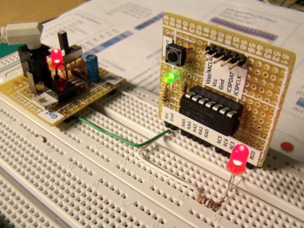
In this article, our author Mithun has developed a 0 – 99 min counter using PIC microcontroller 16F628A. So basically this is a digital count down timer ideal for engineering and diploma students for their project requirements. We have given complete circuit diagram of the digital count down timer along with full source code. In addition, photographs of the breadboard setup is uploaded.

Every micro controller has a timer unit inside. A timer is nothing more than a time counting device fabricated inside the micro controller unit. A wide range of practical applications require a timer in action.
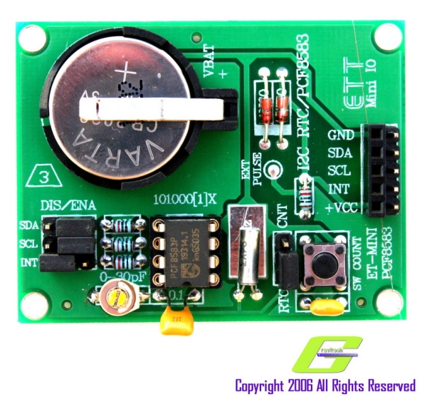
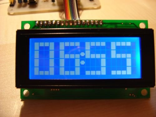
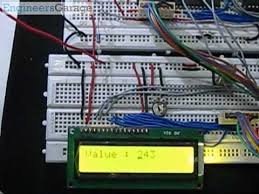
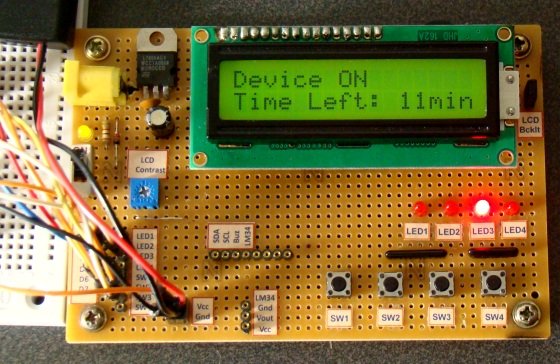
Digital Count Down Timer using PIC MicrocontrollerFor example, we need to turn a motor ON for 5 minutes and then turn it OFF as part of a particular project; how will we do that? A timer inside a mircocontroller unit aids us in implementing this perfectly. A timer can be used to count the 5 minutes exactly and the bits that get SET at 5 minutes limit can be used to program the controller to turn OFF some device(s).

I hope you got a basic idea about timer unit and its practical applications. We are going to make this project using an LCD display, PIC controller 16F628A and a 4 MHz external crystal to provide the necessary clock. We will be writing the codes using micro C.

In any project that involves an LCD, the first step is to initialize the LCD module. We have written detailed articles about interfacing LCD to an MCU before. You can learn more about Interfacing an LCD to 8051  and Interfacing LCD module to AVR controller in these articles. If you want to learn more about character LCD displays in detail, this tutorial on Character LCD displays will be of help.

Now, we need to configure relay and switches. The code snippet for the same is given below.

Here ‘sbit’ stands for set bit. You can do the same another way using “#define” command. This line means that  RA3 pin will be known as the Relay/ RB0 pin will be known as etc.

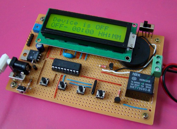
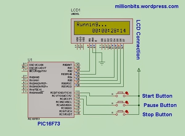
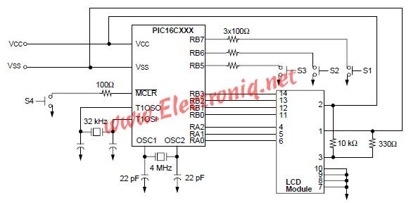
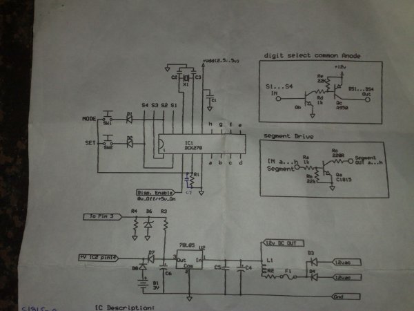
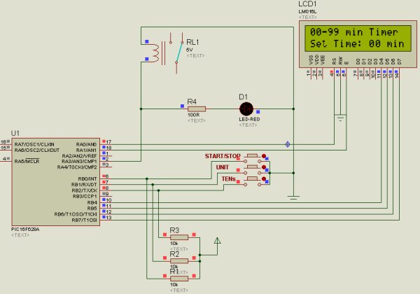
Even though the project name “digital count down timer” sounds so silly, its operation is not that simple. We have given below a proteus diagram of the circuit to explain the project perfectly.

Analyzing the circuit diagram, you can see three buttons . One button is for Start/Stop function and the other 2 buttons for Units & Tens counting. We will configure our LCD module with display messages corresponding to the button configurations

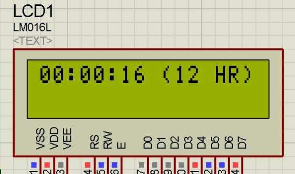
These are the messages we will be showing in our LCD. To control the system we’ll need some other variables as well. These variables are declared in the code snippet given below.
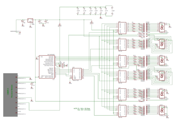
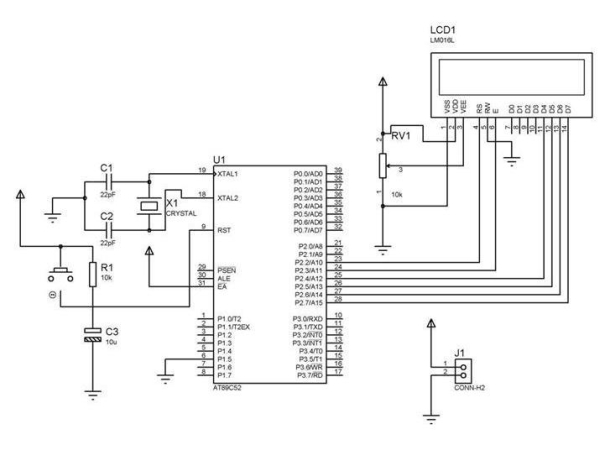
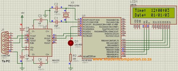
Digital Count Down Timer using PIC Microcontroller SchematicLets understand the counting mechanism now.  The circuit is wired in such a way that, the user will have to select the limit of counting initially. If the user is interested in counting 1 to 9 minutes only, then he is supposed to press the units button alone. If he is interested in counting 1 to 99 minutes, then he should press the Tens button along with Units button.  Once he sets the limit, he should press the Start/Stop button to start the timer (its a push button switch and same button switch is used to stop the timer as well).

Note:- Since the timer operation depends upon the value selected by user (units and tens switch), we have to check certain possible error conditions before starting the timer. Assume a condition in which the user forgot to select units or tens switch and pressed the start/stop button directly; what is supposed to happen in this scenario? It’s an expected error condition that should be handled inside the software. A common way to handle this scenario is to start the timer only if the limit value is greater than zero. The code snippet given below handles this condition.


For more detail: Digital Count Down Timer using PIC Microcontroller

Current Project / Post can also be found using:

  • real time clock mikroc 7 segment

The post Digital Count Down Timer using PIC Microcontroller appeared first on PIC Microcontroller.

Hard Drive Clock using PIC16F628

$
0
0

ave an old hard drive that no longer works? As long as it still spins up chances are you could build a clock out of your old hard drive!

You will need some electronic knowledge, some common electronic components and a bit of
patience. The clock that is produced isn’t exactly practical since most hard drives (especially older ones) are too loud for a clock that is to operate 24 hours a day.

hard-drive-clock

VIDEOS

Watch a video (1.5MB) of the clock in operation!It takes the clock a sew seconds for the speed to stabilize, during this time there is a random pattern of lights that is displayed. After this the clock starts up. It is shown starting at 2:40:00.

Another video (4.7MB) this one shows the clock time being set.Three buttons on the back allow clock adjustment. The purple second hand resets to the zero mark when it’s button is pressed. The blue minute hand increments through each minute and the red hour hand increments through each hour. The position of the hour hand is also dependent on the minute hand. For example the time is 2:30 the hour hand will be pointing at the 12 minute mark.

OVERVIEW

  • Uses 12 high power LEDs for displaying the clock hands, 6 Blue and 6 Red.
  • Slot cut into upper drive platter and white tape on center drive platter provides a slot that when illuminated by the LEDs will represent a clock hand.
  • Minute hand is represented by blue light, hour hand is represented by red light and the second hand is represented by purple (both blue and red on at the same time).
  • Infrared Beam sensor and drilled index hole in lower drive platter.
  • Three micro switches to set hours, minutes and seconds.
  • Custom programmed PIC16F628 microcontroller to control clock operation.

Be informed when new projects are available or additional project information is posted by signing up to our mailing list.

STEPS TO CONSTRUCT CLOCK

1) Select Drive: Find an old hard drive that can spin up when power is connected, you may have to disconnect the 40 pin data cable to see that it can spin up. The drive must spin counter clockwise.

2) Open Drive: Open the drive and see that there are three platters in the unit. We will need three since the top one will have a slot cut into it, the second one will have a piece of white tape (or some other highly reflective material attached. And the third platter will have an index hole drilled into it, this index hole will be used to determine where the slot is when it is spinning. It could still work using a two platter drive but the top of the infrared beam sensor would be visible when a hand is over it.

3) Cut Slot: Remove the screw in the center of the platters, this should allow the platters to be removed. Cut a slot into the 1st platter, I clamped the platter into a vice protecting the surface with cardboard so it wouldn’t scratch. A grinder was then used to cut the grove. It was very easy to cut since it was made of aluminum. NOTE: The top platter that I ended up using was from a more modern drive. The older drive had platters that were dark brown and not very reflective, the modern drive had platters that had a silver mirror finish.


For more detail: Hard Drive Clock using PIC16F628

Current Project / Post can also be found using:

  • PIC 16F84A based stopwatch for athletics
  • digital clock using pic16f877a program
  • seven segment digital time mplab hitech
  • four channel digital timer using pic controller

The post Hard Drive Clock using PIC16F628 appeared first on PIC Microcontroller.

PIC16F84A timer0 code and Proteus simulation

$
0
0

This post provides the timer0 code for PIC16F84A microcontroller. This code is written in C language using MPLAB with HI-TECH C compiler. You can download this code from the ‘Downloads‘ section at the bottom of this page.

PIC16F84A timer0

It is assumed that you know how to blink an LED with PIC16F84A microcontroller. If you don’t then please read this page first, before proceeding with this article.

The result of simulating the code in Proteus is shown below.

In this circuit, PIC16F84A is running on external crystal of 20MHz value. RA0 pin is toggled every time timer0 expires and executes it’s ISR[1] code. In the above figure, it is clear that after approximately every 100usec, RA0 pin is toggled i-e timer0 expires. You can easily change this value in the code.

Code

The code used to initialize timer0 is shown below.

In this function, OPTION_REG is initialized to make timer0 prescalar to be 1:2. Timer0 is an 8bit timer, so it expires after reaching a value of 255. When timer0 prescalar is made 1:2 then it means that timer0 value will increment after every two clock cycles. Since PIC16F84A is running at 5MIPS[2] speed, this means that timer0 will expire after every 256*2/5 = 102 usec[3]. T0IE bit enables timer0 interrupts and GIE bit enables global interrupts.
PIC16F84A timer0 schematic
Timer0 interrupt service routine code is shown below.

Downloads

Timer0 code for PIC16F84A was compiled in MPLAB v8.85 with HI-TECH C v9.83 compiler and simulation was made in Proteus v7.10. To download code and Proteus simulation click here.


For more detail: PIC16F84A timer0 code and Proteus simulation

Current Project / Post can also be found using:

  • DCF77 PIC Hi-Tech
  • clock program for pic microcontroller
  • clock project for pic using c compiler
  • digital big clock by PIC16F877

The post PIC16F84A timer0 code and Proteus simulation appeared first on PIC Microcontroller.

IN-8 single nixie tube clock using PIC16F84

$
0
0

After receiving one IN-8 tube from a friend (thanks), I decided to build myself a clock. This clock is more an ornament than a useful machine because it consists of just one digit (tube) so it displays current time every minute for three times. It is built inside of an old wooden box and it’s powered from a 7V DC wall adapter. Under a nixie tube there is a very bright green LED which makes everything look more beautiful. When time is not displayed, this LED blinks with 1 second period (seconds counter).

nixie tube clock

To power-up a nixie, some 170V DC is required, which means that there is a step-up converter on board with MC34063A IC.

You can download the project files at the bottom of this page by clicking on red “download” button.

Setting up the time
To set the time press the button and power-up the clock. This will enter the programming mode. Now 00, 00, 00,… will be displayed. Press and hold the button until hours are set. Release the button to switch to minutes. Now do the same thing with the minutes and that’s it! After programming, the current time will be displayed.

Timekeeping and measuring
Inside of this box there is a 3V Lithium battery (CR2032) that keeps the PIC microcontroller running even when the clock is turned off (the wall adapter). This is very convenient because after powering it up again, we don’t need to set the time – again. If a button is pressed during a power-down, nothing will happen. With PIC microcontroller I used a “watch” crystal at 32,768kHz. It’s value is pretty cool and now we will see why. PIC16F84 has internal TMR0 counter that increments itself no matter what the PIC is doing at the moment.


For more detail: IN-8 single nixie tube clock using PIC16F84

Current Project / Post can also be found using:

  • What is the use of clock in pic microcontroller
  • clock pic pic
  • design and construction of digital clock calender using pic 16f48a
  • digital clock mikroc code using leds

The post IN-8 single nixie tube clock using PIC16F84 appeared first on PIC Microcontroller.

Determine capacitance by measuring the charging time using PIC16F688

$
0
0

When TEST botton is pressed, RA3 pin is set to “1”. R2 and R3 are divide the voltage to 1/2 Vra3 which is connected to RA2 pin to be a Vref for comparator. The C undertest is charging and the timer is start. When the voltage of C undertest is more than 1/2 or above Vref, the timer is stop. and a number of periods that elapsed multiply by 10 is the C value in nF. Convert C number to string and display to 1×16 LCD.

Circuit

The code

/*
* Project name:
Capacitance Meter
* Copyright:
Nicholas Sirirak
* Description:

* Test configuration:
MCU: PIC16F88
Dev.Board: –
Oscillator: HS, 8.0000 MHz internal
Ext. Modules: –
SW: mikroC v8.1.0.0
* NOTES:

*/

#define Vappied PORTA.F3
#define TEST PORTA.F0
unsigned int gCap = 0;
char gOverTest = 0;
char gMessage[8];
char gCapstr[8];
void interrupt(){
if(PIR1.TMR2IF){
TMR2 = 0x87; // best value to create 69.3us
gCap++;
if(gCap > 65500) gOverTest = 1;
PIR1.TMR2IF =0; // Clear int bit
}
}

void main(){
char i,j;
char cap_size;
ANSEL = 0;
TRISB = 0;
PORTB = 0;
OSCCON = 0x7E; // 8Mhz, RC internal clock
OPTION_REG.T0CS = 0;
INTCON.GIE = 1; //Enable global interrupt
INTCON.PEIE = 1; //Enable peripheral interrupt
//———— Set up Timer2 ————
PIE1.TMR2IE = 1;
T2CON = 0; // timer2 off, prescaler 1:1
TMR2 = 0x87;
PIR1.TMR2IF =0; // Clear int bit
//—————————————-


For more detail: Determine capacitance by measuring the charging time using PIC16F688


Current Project / Post can also be found using:

  • real time clock using pic microcontroller without rtc

The post Determine capacitance by measuring the charging time using PIC16F688 appeared first on PIC Microcontroller.

Viewing all 218 articles
Browse latest View live


<script src="https://jsc.adskeeper.com/r/s/rssing.com.1596347.js" async> </script>