Quantcast
Channel: Clock - Timer Projects - PIC Microcontroller
Viewing all 218 articles
Browse latest View live

Real time clock with 2 alarms and temperature sensing using PIC18F4550 and DS3231

$
0
0

DS3231 with alarm PIC18F4550 hardware circuit

After the simple interfacing of the PIC18F4550 microcontroller with the DS3231 RTC, now let’s add the alarms functionality and temperature monitor to our previous project.
Interfacing PIC18F4550 with DS3231 project link:
Real time clock & calendar with PIC18F4550 and DS3231
As written in the datasheet the DS3231 RTC has a built-in 2 alarm functions and a digital temperature sensor with an accuracy of ±3°C.
Hardware Required:

  • PIC18F4550 microcontroller
  • 20×4 LCD screen
  • 10K ohm variable resistor
  • 330 ohm resistor
  • LED
  • 3 x push button
  • 5V supply source
  • Breadboard
  • Jumper wires

DS3231 board contains the following components:

  • DS3231 RTC – datasheet
  • 3 x 4.7K ohm resistors
  • 0.1uF ceramic capacitor
  • 3V coin cell battery

The circuit:
Project circuit diagram is shown below.

ds3231-real-time-clock-calendar-alarm-temperature-pic18f4550-circuit

To simplify the circuit, I used the DS3231 board, this board basically contains the main chip which is the DS3231, pull-up resistors (4.7K) of SCL, SDA and INT/SQW lines and coin cell battery holder. There is also 24C32 EEPROM and some other resistors (not used in this project).
The DS3231 board is supplied with 5V as the microcontroller and the 2004 LCD, there are 3 data lined connected between this board and the PIC18F4550 MCU, SCL line is connected to pin RB1, SDA is connected to pin RB0 and INT line is connected to pin RB2 which is the external interrupt 2 pin of the PIC18F4550 MCU. The DS3231 interrupts the microcontroller when there is an alarm.

In the circuit there are 3 push buttons: B1, B2 and B3. These buttons are used to set time, calendar and alarms. Time and calendar can be adjusted with B1 and B2, button B1 selects time or date parameter (time parameters: hours and minutes; calendar parameters: day, date, month and year) and B2 increments the selected parameter. The button B3 and B2 adjust alarm1 and alarm2 parameters (hours, minutes and ON/OFF), button B3 selects the parameter and B2 increments the selected parameter.
There is an LED connected to pin RB6, this LED is used as an alarm indicator (alarm1 or alarm2), so if there is an alarm the DS3231 pulls down the INT pin which interrupts the microcontroller and the microcontroller turns the LED ON, here button B2 turns both the LED and the occurred alarm OFF.
In this project the PIC18F4550 MCU uses its internal oscillator and MCLR pin function is disabled.
CCS C code:
The C code below was tested with CCS C compiler version 5.051.
By reading the datasheet of the DS3231 RTC the code will be more easier!
The hardware I2C module of the MCU is initialized and configured using the following CCS C function with a speed of 100KHz:
#use I2C(master, I2C1, FAST = 100000)

master: set the microcontroller to the master mode

I2C1: use first I2C module.
The DS3231 works with BCD format only (except temperature) and to convert the BCD to decimal and vise versa I used the following functions (example for minute variable):
minute = (minute >> 4) * 10 + (minute & 0x0F);                                  // Convert BCD to decimal
minute = ((minute / 10) << 4) + (minute % 10);                                   // Convert decimal to BCD
Code functions:
void DS3231_read() : this function reads time and calendar data from the DS3231 (seconds, minutes, hours, day, date, month and year).
void DS3231_display() : displays time and calendar data, before displaying time and calendar data are converted from BCD format to decimal format. This function displays the calendar by calling a function named void calendar_display() .
void alarms_read_display() : basically this functions reads alarm1 and alarm2 minutes and hours. It also reads the DS3231 control register, status register and 2 temperature registers.
The other job of this function is to display alarms data (hours, minutes and status) and the temperature value. The alarm status are extracted from the control register.
int8 edit(parameter, x, y) : I used this function to edit time, calendar and alarm parameters except the day. I used a variable named i to distinguish between the parameters:
i = 0, 1 : time hours and minutes respectively
i = 2, 3, 4: date month, year respectively
i = 5, 6: alarms hours and minutes respectively
i = 7: alarms status (ON or OFF)
After the edit of time/calendar/alarms the data have to be converted back to BCD format and written to the DS3231.
for more detail:  Real time clock with 2 alarms and temperature sensing using PIC18F4550 and DS3231

The post Real time clock with 2 alarms and temperature sensing using PIC18F4550 and DS3231 appeared first on PIC Microcontroller.


Real time clock with remote control and ST7735 TFT display

$
0
0

(Some knowledge about RC-5 protocol is required)
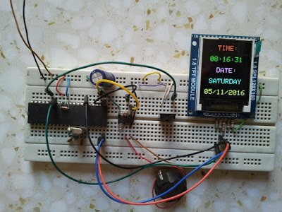
This project shows how to build a remote controlled real time clock with TFT display using PIC18F4550 microcontroller.
In this project DS1307 RTC is used as a real time clock chip and the remote control is an IR (infrared) remote control which uses RC-5 communication protocol, this remote control is used to set time and date. The device used t display time and calendar is 1.8″ ST7735R (ST7735S) SPI TFT display.Real time clock with remote control and ST7735 TFT display

To display the ST7735 TFT display with PIC18F4550 microcontroller we need a driver, this driver and some other details about this display can be fount at the following url:
ST7735 SPI TFT Display Driver for CCS PIC C compiler
And the post at the following link shows how to interface this display with PIC18F4550 microcontroller:
Interfacing PIC18F4550 with 1.8″ TFT display
Or simply you can download the ST7735 TFT driver from the following link:
ST7735 SPI TFT Display Driver
The method used to decode RC-5 signals is described in the following topic:
RC5 IR Remote Control Decoder with PIC12F1822 Microcontroller
The decoding process follows the state machine show below:tate machine Real time clock with remote control and ST7735 TFT display

Where:
SP : Short Pulse (About 889µs)
LP : Long Pulse (About 1778µs)
SS: Short Space (About 889µs)
LS : Long Space (About 1778µs)
Basically there are 4 states: Mid1, Mid0, Start1 and Start0.
Components List:

  • PIC18F4550 Microcontroller
  • ST7735R (ST7735S) 1.8″ SPI TFT Display
  • DS1307 RTC Chip
  • RC-5 IR Remote Control
  • IR Receiver
  • 8MHz Crystal Oscillator
  • 32.768KHz Crystal Oscillator
  • 2 x 22pF Ceramic Capacitors
  • 47uF Capacitor
  • 3 x 10K Resistor
  • 5 x 1K Resistors
  • 3V Lithium Coin Cell Battery
  • +5V Power Supply Source
  • Breadboard
  • Jumper Wires

For the DS1307 RTC chip there are many topics in this blog talking about it and how to interface it with different types of PIC microcontrollers for example the topic at the url below:
Real time clock with PIC18F4550 and DS1307 RTC
Real time clock with remote control and ST7735 TFT display circuit:
The following image shows our project circuit schematic where the microcontroller runs with 8MHz external crystal oscillator.

For more Detail: Real time clock with remote control and ST7735 TFT display

The post Real time clock with remote control and ST7735 TFT display appeared first on PIC Microcontroller.

Time-Controlled Switch Using PIC16F72

$
0
0

A time controlled switch is an automatic timer switch that turns an appliance ‘on’ for the desired time duration. After the preset time duration, the timer automatically switches off, disconnecting the appliance from the power supply. The time duration for which the appliance should be ‘on’ can be set from 1 to 99 minutes.

This switch obviates the need to continuously monitor the appliance—an advantage over the manual switch. It can be used to switch on or switch off any electrical home appliance at a predetermined time. Switching an appliance on or off in a timely manner increases the life of the appliance and also saves power consumption.

The switch also finds industrial applications, where the machines which control the processes can be run for the desired time.

Time controlled switch circuit

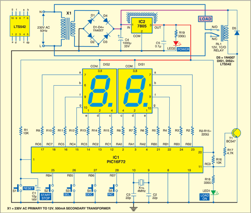
Fig. 1 shows the circuit of the time controlled switch using PIC16F72 microcontroller. It comprises microcontroller PIC16F72 (IC1), regulator 7805 (IC2), two 7-segment displays//electronicsforu.com/resources/7-segment-display-pinout-understanding(LTS542) and a few discrete components.

Microcontroller PIC16F72 is the heart of this time controlled switch. It is an 8-bit, low-cost, high-performance, flash microcontroller. Its key features are 2 kB of flash program memory, 128 bytes of RAM, eight interrupts, three input/output (I/O) ports, three timers and a five-channel 8-bit analogue-to-digital converter (ADC). There are 22 I/O pins, which are user-configurable for input/output on pin-to-pin basis. Architecture is RISC, and there are only 35 powerful instructions.

System clock plays a significant role in operation of the microcontroller. A 4MHz quartz crystal connected between pins 9 and 10 provides the basic clock to the microcontroller (IC1).

Two 7-segment displays (DIS1 and DIS2) are used to display the time in minutes. Port pins RB2, RB3, RA0, RA1, RA2, RB1 and RB0 are connected to segment pins ‘a’ through ‘g’ of display DIS1, respectively. Ports pin RC6, RC7, RC1, RC2, RC3, RC5 and RC4 are connected to segment pins ‘a’ through ‘g’ of display DIS2, respectively.

Switches S2 (start/stop), S3 (select), S4 (decrement) and S5 (increment) are connected to port pins RB4 through RB7 of the microcontroller, respectively. Port pin RC0 of the microcontroller is used to control relay RL1 with the help of transistor T1. When port pin RC0 is high, transistor T1 drives into saturation and 12V-relay RL1 energises to connect the load to power supply. Diode D5 acts as a free-wheeling diode.

Circuit Operation

To derive the power supply for the circuit, the 230V, 50Hz AC mains is stepped down by transformer X1 to deliver a secondary output of 12V, 500mA. The transformer output is rectified by a full-wave rectifier comprising diodes D1 through D4, filtered by capacitor C4 and regulated by IC 7805 (IC2). Capacitor C5 is used to bypass the ripples present in the regulated supply. LED2 gives power-‘on’ indication. Resistor R19 limits the current through LED2. Switch S1 is used for manual reset.

Set the time using switch S4 for decrement and switch S5 for increment. The time is indicated on 7-segment displays DIS1 and DIS2. To start timing count-down, press start/stop switch S2. Relay RL1 energises to switch on the appliance and LED1 glows. If you press start/stop switch S2 again, the count-down process will stop and relay RL1 de-energise to switch the appliance off.

Construction and working

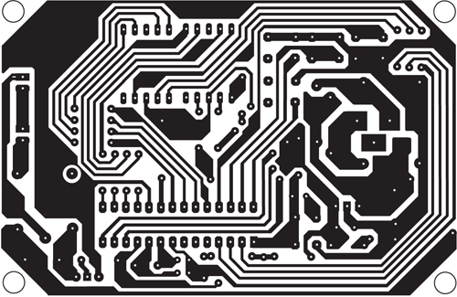
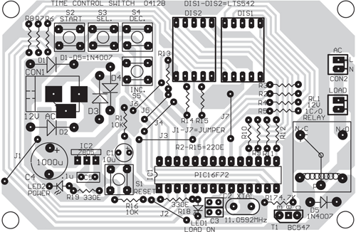
A single-side PCB for the microcontroller-based time controlled switch is shown in Fig. 2 and its component layout in Fig. 3.

Fig. 2: An actual-size, single-side PCB for the time-controlled switch using PIC16F72
Fig. 2: A single-side PCB for the time controlled switch using PIC16F72
Fig. 3: Component layout for the PCB

Download PCB and component layout PDFs: click here

Assemble the circuit on a PCB to minimise time and assembly errors. Carefully assemble the components and double-check for any overlooked error. Use an IC base for microcontroller. Before inserting the IC, check the supply voltage.

The time controlled switch works in two modes: setting mode (to set the time from 1 to 99 minutes) and working mode (to drive the load for the desired time as per the setting). The modes can be changed using switch S3. When LED1 glows, it indicates that the system is in working mode. If LED1 is off, the system is in setting mode.

Setting mode

By default, when the microcontroller is powered up, it is in setting mode. In this mode, one of the two 7-segment displays should blink with a random digit, say, 6. You can change the blinking digit to any digit from 0 through 9 using decrement switch S4 or increment switch S5. You can also shift the blinking digit from DIS1 to DIS2 or vice-versa using switch S3. Thus the desired time can be set using switches S3, S4 and S5.

After setting the desired time, press start/stop switch S2 to switch from setting mode to working mode. The appliance will turn on for the preset time unless you press switch S2 again to stop the operation in between.

The post Time-Controlled Switch Using PIC16F72 appeared first on PIC Microcontroller.

DS1307 Based Hand Clock with seven segment display using PIC16F877A

$
0
0

DS1307 Based Hand Clock with seven segment display using PIC16F877A (Code)


//------Project by { ZAKI }--"facebook.com / Zaki Semel"----------//
//------Project { Clock Hand }---For Pic16f877a & 7 Segment 4, Anode-------//
//*****************************************************************************//
char second, minute, hour, day, date, month, year;
char second_d1, second_d2, minute_d1, minute_d2, hour_d1, hour_d2;
char date_d1, date_d2, month_d1, month_d2, year_d1, year_d2, year_d3, year_d4;
char convert, hold;
char seg[]={0xc0, 0xf9, 0xa4, 0xb0, 0x99, 0x92, 0x82, 0xf8, 0x80, 0x90}; //Segment 0-9
//----Buttons-----------------------------//
#define Button1 PORTC.f0 //Show Date & Second, Date & Second ++
#define Button2 PORTC.f1 //Change Time & Date
#define Button3 PORTC.f2 //Show Time & No Save Time & Date
#define Button4 PORTC.f5 //Show Year
//----In Interrupt-----------------------------------//
#define GotoTime 0
#define GotoSecond 1
#define GotoDate 2
#define GotoYear 3
#define GotoClear 4
//----Hour 12 (AM-PM)---------------------//
#define AM PORTE.f0 //Hour12(AM)
#define PM PORTE.f1 //Hour12(PM)
//-----Display Time------------------//
void DisplayTime()
{
char x;
second_d1 = seg[second /10];
second_d2 = seg[second %10];
minute_d1 = seg[minute /10];
minute_d2 = seg[minute %10];
hour_d1 = seg[hour /10];
hour_d2 = seg[hour %10];
date_d1 = seg[date /10];
date_d2 = seg[date %10];
month_d1 = seg[month /10];
month_d2 = seg[month %10];
year_d1 = seg[year /10];
year_d2 = seg[year %10];
year_d3 = seg[year /10];
year_d4 = seg[year %10];
}
//----I2C Read for IC DS1307----------------//
void ReadI2C()
{
i2c1_start();
i2c1_wr(0xd0);
i2c1_wr(0);
i2c1_repeated_start();
i2c1_wr(0xd1);
second = i2c1_rd(1);
minute = i2c1_rd(1);
hour = i2c1_rd(1);
day = i2c1_rd(1);
date = i2c1_rd(1);
month = i2c1_rd(1);
year = i2c1_rd(0);
i2c1_stop();
}
//----Transform Time for IC DS1307------------------//
void TransformTime()
{
second =((second & 0xf0)>>4)* 10 +(second & 0x0f);
minute =((minute & 0xf0)>>4)* 10 +(minute & 0x0f);
hour =((hour & 0xf0)>>4)* 10 +(hour & 0x0f);
day =((day & 0xf0)>>4)* 10 +(day & 0x0f);
date =((date & 0xf0)>>4)* 10 +(date & 0x0f);
month =((month & 0xf0)>>4)* 10 +(month & 0x0f);
year =((year & 0xf0)>>4)* 10 +(year & 0x0f);
}
//----Start Time for IC DS1307------------------------------//
void StartTime(char second, char minute, char hour, char day, char date, char month, char year)
{
i2c1_start();
i2c1_wr(0xd0);
i2c1_wr(0);
i2c1_wr(second);
i2c1_wr(minute);
i2c1_wr(hour);
i2c1_wr(day);
i2c1_wr(date);
i2c1_wr(month);
i2c1_wr(year);
i2c1_wr(0x10); // 1Hz
i2c1_stop();
}
//----Save Time & Date for Change------------------//
void SaveTime()
{
i2c1_start();
i2c1_wr(0xd0);
i2c1_wr(0);
i2c1_wr(dec2bcd(second));
i2c1_wr(dec2bcd(minute));
i2c1_wr(dec2bcd(hour));
i2c1_wr(dec2bcd(day));
i2c1_wr(dec2bcd(date));
i2c1_wr(dec2bcd(month));
i2c1_wr(dec2bcd(year));
i2c1_stop();
}
//----Hour 12 (AM-PM)----------------------//
void Hour12_AM_PM()
{
if (hour < 0x12) { if (hour == 0) { hour = 0x12; AM = 1; } else AM = 1; } else if (hour == 0x12) { PM = 1; } else if (hour > 0x12 && hour < 0x20) { hour = hour - 0x12; PM = 1; } else if (hour == 0x20) { hour = 0x08; PM = 1; } else if (hour == 0x21) { hour = 0x09; PM = 1; } else if (hour == 0x22) { hour = 0x10; PM = 1; } else if (hour == 0x23) { hour = 0x11; PM = 1; } } //----Show Date & Second for Button1-------------------// void DateSecond(char set) { switch(set) { case 0: convert = GotoDate; break; //Goto Date in Interrupt case 1: convert = GotoSecond; break; //Goto Second in Interrupt } } //----Show Date & Second for Button1-------------------// void MenuDateSecond() { char set; set = 0; while(1) { ReadI2C(); Hour12_AM_PM(); TransformTime(); DisplayTime(); DateSecond(set); if (Button1 == 0){hold = 1;} if (Button1 == 1 && hold == 1) { hold = 0; set++; if (set > 1)
{
delay_ms(2);
convert = GotoTime; //Goto Time in Interrupt
break;
}
}
//-----------------------------//
if (set >= 1)
{
if (Button2 == 1) //---Second = 0
{
second = 0;
SaveTime(); //---Save Time
}
}
}
}
//*****************************************//
//----Change Time & Date for Button2----------------------//
void SetChangeTime(char set)
{
switch(set)
{
case 0:
hour_d1 = hour_d2 = 0xff; delay_us(500);
break;
case 1:
minute_d1 = minute_d2 = 0xff; delay_us(500);
break;
case 2:
date_d1 = date_d2 = 0xff; delay_us(500);
break;
case 3:
month_d1 = month_d2 = 0xff; delay_us(500);
break;
case 4:
year_d3 = year_d4 = 0xff; delay_us(500);
break;
}
}
//----Change Time & Date for Button2----------------------//
void ChangeTime(char set, char change)
{
switch(set)
{
case 0:
if (change == 0)
{
hour ++;
if (hour > 23) hour = 0;
}
break;
case 1:
if (change == 0)
{
minute ++;
if (minute > 59) minute = 0;
}
break;
case 2:
if (change == 0)
{
date ++;
if (date > 31) date = 1;
}
break;
case 3:
if (change == 0)
{
month ++;
if (month > 12) month = 1;
}
break;
case 4:
if (change == 0)
{
year ++;
if (year > 99) year = 0;
}
break;
}
}
//----Change Time & Date for Button2----------------------//
void MenuChangeTime()
{
char set;
set = 0;
while(1)
{
DisplayTime();
SetChangeTime(set);
if (Button2 == 0){hold = 1;}
if (Button2 == 1 && hold == 1)
{
hold = 0;
set ++;
if (set > 4) //Save Time
{
convert = GotoTime; //Goto Time in Interrupt
second = 0;
SaveTime();
break;
}
if (set > 1) convert = GotoDate; //Goto Interrupt
if (set > 3) convert = GotoYear; //Goto Interrupt
}
if (Button1 == 1) //Time & Date ++
{
SetChangeTime(set);
ChangeTime(set, 0); //Time & Date ++
}
if (Button3 == 1) //No Save, Goto Normal Time
{
convert = GotoTime; //Goto Time in Interrupt
break;
}
}
}
//----Clear Display-------------------------//
void ClearDisplay()
{
while(1)
{
convert = GotoClear; //Goto Clear in Interrupt
ReadI2C();
TransformTime();
portE = 0;
if (Button1 == 0 && Button2 == 0){hold = 1;}
if (Button1 == 1 && hold == 1) //Show Date & Second
{
hold = 0;
convert = GotoDate; //Goto Interrupt
MenuDateSecond(); //Goto MenuDateSecond();
break;
}
if (Button2 == 1 && hold == 1)
{
hold = 0;
convert = GotoTime; //Goto Time in Interrupt
MenuChangeTime();
break;
}
if (Button3 == 1)
{
convert = GotoTime; //Goto Time in Interrupt
break;
}
if (Button4 == 1)
{
convert = GotoYear; //Goto Year in Interrupt
break;
}
}
}
//----Interrupt-------------------------------//
void Interrupt()
{
if (convert == GotoSecond) //Show Second
{
portd = 1; portb = 0xff; delay_ms(1);
portd = 2; portb = 0xff; delay_ms(1);
portd = 4; portb = second_d1; delay_ms(1);
portd = 8; portb = second_d2; delay_ms(1);
}
if (convert == GotoTime) //Show Time(Hour & Minute)
{
portd = 1; portb = hour_d1; delay_ms(1);
portd = 2; portb = hour_d2 + 128; delay_ms(1);
portd = 4; portb = minute_d1; delay_ms(1);
portd = 8; portb = minute_d2; delay_ms(1);
}
if (convert == GotoDate) //Show Date(Date & Month)
{
portd = 1; portb = date_d1; delay_ms(1);
portd = 2; portb = date_d2 + 128; delay_ms(1);
portd = 4; portb = month_d1; delay_ms(1);
portd = 8; portb = month_d2; delay_ms(1);
}
if (convert == GotoYear) //Show Year
{
portd = 1; portb = 0xa4; delay_ms(1);
portd = 2; portb = 0xc0; delay_ms(1);
portd = 4; portb = year_d3; delay_ms(1);
portd = 8; portb = year_d4; delay_ms(1);
}
if (convert == GotoClear) //Clear Display
{
portd = 1; portb = 0xff; delay_ms(1);
portd = 2; portb = 0xff; delay_ms(1);
portd = 4; portb = 0xff; delay_ms(1);
portd = 8; portb = 0xff; delay_ms(1);
}
intcon = 0b10100000;
}
//*********** Main *******************************************//
void main()
{
trisB = 0; trisC = 0xff; trisD = 0; trisE = 0;
option_reg = 0b10000000; intcon = 0b10100000; //Registers
i2c1_init(100000); //Init I2C(IC DS1307)
StartTime(0x00, 0x00, 0x00, 0, 0x21, 0x03, 0x17); //Start Time
while(1)
{
ReadI2C();
Hour12_AM_PM();
TransformTime();
DisplayTime();
delay_ms(10);
ClearDisplay(); //Goto ClearDisplay()
}
}

DS1307 Based Hand Clock with seven segment display using PIC16F877A (Schematic Diagram)

DS1307 Based Hand Clock with seven segment display using PIC16F877A

hand clock using pic

The post DS1307 Based Hand Clock with seven segment display using PIC16F877A appeared first on PIC Microcontroller.

The Weeder Frequency Counter using PIC16F84

$
0
0

This is a port by Peter Cousens to the PIC 16F84 of the  50Mhz Frequency counter kit {originally available} from Weeder Technologies . Since it uses a base PIC that is easily programmable, and provides a usefull bit of bench test equipment at very low cost, it makes an ideal PIC learning project. If you don’t want to spend the time on the PCB, collecting the parts or even not programming the uP, you can order the kit (for a very resonable price) from http://www.weedtech.com

Weeder Frequency Counter

News: Weeder Tech no longer makes this kit. They have moved on to a very nice version that works with a local PC via the serial port for display and control. It is also “stackable” for multiple counters at once or with other modules for control and measurement of all kinds. See
http://www.weedtech.com for more information. The original kit has been licenced to Invent Electronics and Ken has made some improvements and provides a very nice (closed source) kit for $49 and a PCB for $10 (prices as of 2004/03/05)

The result is a nice frequency counter that reads frequency from 1 Hz to 50 MHz and displays it on a 16 character LCD display. Auto-range feature provides floating decimal point and automatic placement of suffix (Hz, KHz, or MHz). Gate speed automatically decreases to one second below 100 KHz to display frequency with a resolution down to an amazing 1 Hz.

  • Auto-ranging with floating decimal point.
  • Up to 7 digits displayed.
  • Auto-adjusting gate speed (0.1 sec to 1 sec).
  • Microcontroller-based circuitry provides for simplicity, ease of assembly, and highly stable readout.
  • Sensitivity approximately 100 mV RMS (100 Hz to 2 MHz), 800 mV RMS @ 50 MHz.
  • Input overload protected.


For more detail: The Weeder Frequency Counter using PIC16F84

The post The Weeder Frequency Counter using PIC16F84 appeared first on PIC Microcontroller.

10MHz DDS Sine/Square Function Generator based on the AD9835 using PIC16F628

$
0
0

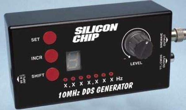
An extremely simple and low cost Sine/Square wave generator based on the Analog Devices AD9835 Direct Digital Synthesis (DDS) Generator chip. The frequency can be set for any frequency from 1Hz to 10MHz in 1Hz resolution steps! All this with three push buttons and a novel “sliding window” LED display. The controller chip is a Microchip PIC16F628. There is no wiring, and the PCB fits into a standard UB3 Jiffy Box.

Square Function Generator

Read the complete Project Article in HTML format.

The Schematic Diagram in GIF format.

The Front Component Overlay in GIF format.

The Back Component Overlay in GIF format.

The Front Panel in ZIPed PDF format

The Front Panel in ZIPed EPS format

The PCB file in Protel format.

The SOURCE CODE and HEX file for a 16F628 and HiTech PIC C Compiler.

For more detail: 10MHz DDS Sine/Square Function Generator based on the AD9835 using PIC16F628

Current Project / Post can also be found using:

  • 1 hr timer in 12f629
  • using timers pic for clock

The post 10MHz DDS Sine/Square Function Generator based on the AD9835 using PIC16F628 appeared first on PIC Microcontroller.

Single-Tube nixie clock | Microcontroller Project

$
0
0
Here is the nixie clock !
  • PIC16F84A microcontroller
  • Single-digit Nixie, sequential hours, minutes and seconds display
  • DCF-77 atomic clock, with automatic or manual time set-up
  • high voltage power supply for Nixie with only 4 components
  • 24 hours cycle programmable extinction time
  • no MikroC compiler licence needed !

This project will show you how to drive a nixie tube display with a PIC16F84A simple microcontroller.
The nixie is a vertical-mount, front-reading IN-14 russian tube (thanks Alex !), very convenient for prototyping because of its long solderable pins.
How to power the nixie ?

Single Tube nixie clock  Microcontroller ProjectA 170 volt power supply must be applied between the anode of the tube and one of its cathod, to light the corresponding number from 0 to 9. The lightened number needs around 1.5 mA to glow.
If the voltage is lower, the number is not completely lightened and may even extinguish (under 140 V).
If the voltage is higher, digits will randomly light at the same time, and no digit will be clearly readable.
It is possible to get the high voltage from the main power supply, but it is highly dangerous because live parts may be exposed to dangerous voltage.
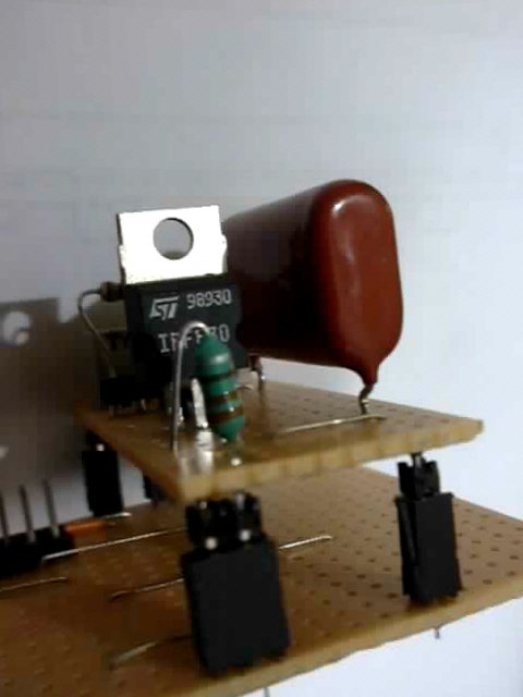
That’s why is use a DC/DC converter, which gives the +170V needed by the nixie from the +5V power supply of the circuit. The PIC16F84A generates a software PWM, and drives the MOSFET’s gate. The MOSFET switches on an off the current into a 300 µH coil. The inducted high voltage is collected by a fast recovery diode and then fed into a capacitor.
This is a close-up view, showing the IRF830 MOSFET, the 330 µH miniature coil, and the big 2.2 µF 250V capacitor.
Note that the power supply is build as an individual board, I use it also in other test boards for other projects.
A simple resistor divider feeds back a voltage reference into a PIC input : if the voltage exceeds the 1 level of the PIC, the software turns PWM off, until the voltage turns under the 1 level of the PIC : then the PWM output starts again, and so on… this allows to keep a constant high voltage of around +170 V, depending on the variable resistor setting.
This is a close-up of the voltage reference divider.
We can also see that the 15 K anode current limiting resistor is mounted on a socket : during tests, a 47 K resistor was used. Remember this : reducing the current will increase the life of your tube ! You have to find a good value for a good brightness and a long life.
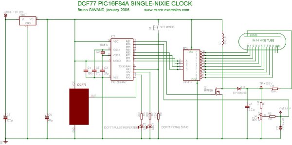
Single Tube nixie clock  Microcontroller Project schematic
Power supply adjustment : turn the variable potentiometer, so that you can read around 175 V on a voltmeter connected to the test point (see schematic). Don’t forget that there is a 2.2 µF capacitor charged with +170 V in the circuit. This is enough to hurt you VERY BADLY if you touch it.
How to drive the nixie ?
The anode is connected to the high voltage through a 15 K resistor, in order to limit the current to approximately 1.5 mA. It is not possible to drive the cathodes with the pic output, because of the high voltage engaged.
I use a 74141 IC, which has been designed for nixie tubes : it includes a BCD to decimal decoder, and each output has a high-voltage transistor.

Current Project / Post can also be found using:

  • trouble free unless the 927379

The post Single-Tube nixie clock | Microcontroller Project appeared first on PIC Microcontroller.

Video Clock Superimposer using PIC16C711

$
0
0

About the Project

As a followup to my VCR Pong project, here is a gadget that is actually useful in the Real World! It superimposes the time of day, in “HH MM SS” format, in the bottom right-hand corner of an existing video signal. My friend Scott uses it with his home security system.

In keeping with the tradition of my previous hacks, I use few parts and lots of tricks. All timing signals, including the timebase for the time of day and the clock for the microprocessor, are derived from the incoming video signal. That means if you lose power, or lose video, it loses the time… but in this home security application, that didn’t matter. Lost power would mean the VCR stops recording and starts flashing 12:00 (1:00 during daylight savings).


Video Clock

Project Files

Here is the schematic, a parts list and circuit description, and most importantly the PIC source code.

The code uses the Parallax instruction syntax, so you’ll either need to use Parallax’s SPASM.EXE (available for free on Parallax’s web site) or Tech-Tools’s CVASM16.EXE (available for evaluation on Tech-Tools’s web site), or here is a preassembled object file, in INXH8M format, for use with any device programmer.


For more detail: Video Clock Superimposer using PIC16C711

Current Project / Post can also be found using:

  • pic16c711 project

The post Video Clock Superimposer using PIC16C711 appeared first on PIC Microcontroller.


Hard Drive Clock using PIC16F628

$
0
0

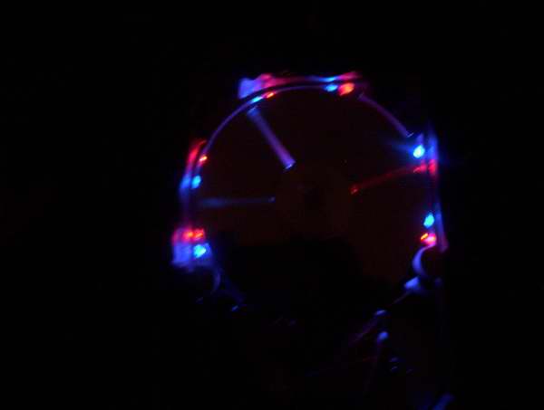
ave an old hard drive that no longer works? As long as it still spins up chances are you could build a clock out of your old hard drive!

You will need some electronic knowledge, some common electronic components and a bit of
patience. The clock that is produced isn’t exactly practical since most hard drives (especially older ones) are too loud for a clock that is to operate 24 hours a day.

hard-drive-clock

VIDEOS

Watch a video (1.5MB) of the clock in operation!It takes the clock a sew seconds for the speed to stabilize, during this time there is a random pattern of lights that is displayed. After this the clock starts up. It is shown starting at 2:40:00.

Another video (4.7MB) this one shows the clock time being set.Three buttons on the back allow clock adjustment. The purple second hand resets to the zero mark when it’s button is pressed. The blue minute hand increments through each minute and the red hour hand increments through each hour. The position of the hour hand is also dependent on the minute hand. For example the time is 2:30 the hour hand will be pointing at the 12 minute mark.

OVERVIEW

  • Uses 12 high power LEDs for displaying the clock hands, 6 Blue and 6 Red.
  • Slot cut into upper drive platter and white tape on center drive platter provides a slot that when illuminated by the LEDs will represent a clock hand.
  • Minute hand is represented by blue light, hour hand is represented by red light and the second hand is represented by purple (both blue and red on at the same time).
  • Infrared Beam sensor and drilled index hole in lower drive platter.
  • Three micro switches to set hours, minutes and seconds.
  • Custom programmed PIC16F628 microcontroller to control clock operation.

Be informed when new projects are available or additional project information is posted by signing up to our mailing list.

STEPS TO CONSTRUCT CLOCK

1) Select Drive: Find an old hard drive that can spin up when power is connected, you may have to disconnect the 40 pin data cable to see that it can spin up. The drive must spin counter clockwise.

2) Open Drive: Open the drive and see that there are three platters in the unit. We will need three since the top one will have a slot cut into it, the second one will have a piece of white tape (or some other highly reflective material attached. And the third platter will have an index hole drilled into it, this index hole will be used to determine where the slot is when it is spinning. It could still work using a two platter drive but the top of the infrared beam sensor would be visible when a hand is over it.

3) Cut Slot: Remove the screw in the center of the platters, this should allow the platters to be removed. Cut a slot into the 1st platter, I clamped the platter into a vice protecting the surface with cardboard so it wouldn’t scratch. A grinder was then used to cut the grove. It was very easy to cut since it was made of aluminum. NOTE: The top platter that I ended up using was from a more modern drive. The older drive had platters that were dark brown and not very reflective, the modern drive had platters that had a silver mirror finish.


For more detail: Hard Drive Clock using PIC16F628

The post Hard Drive Clock using PIC16F628 appeared first on PIC Microcontroller.

A PIC16F84A Alarm Clock

$
0
0

Here is a simple PIC16F84A alarm clock. This page summarizes this discussion (in french) in my forum, where Samir (aka numerique1) requested for help to build a weekly alarm clock for his school. Many thanks to him for his tests and patience.

A Alarm Clock

This clock counts seconds, minutes, hours and day of the week.
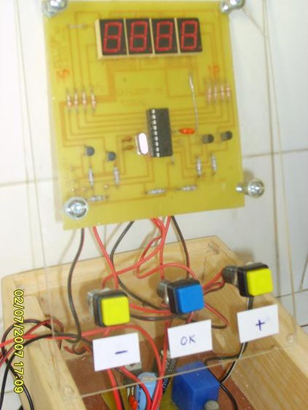
Time is displayed on 4 seven segment LED displays, and is adjustable with three buttons at start time (up, down, enter).
You can program the day of the week, hour, minute and duration of the alarms.
The number of alarms are limited by ROM space only.
The alarm is on the RA4 open collector output of the PIC, and is repeated on a decimal point of the display.

For once, the program is in BASIC (mikroBasic) and I hope it will make a good start for beginners.

First, the BASIC source code.

Schematic A Alarm Clock

Note that you can build it either for common cathod or common anode LED display.


For more detail: A PIC16F84A Alarm Clock

Current Project / Post can also be found using:

  • timer in pic microcontroller pdf

The post A PIC16F84A Alarm Clock appeared first on PIC Microcontroller.

Real time clock with 2 alarms and temperature sensing using PIC18F4550 and DS3231

$
0
0

DS3231 with alarm PIC18F4550 hardware circuit

After the simple interfacing of the PIC18F4550 microcontroller with the DS3231 RTC, now let’s add the alarms functionality and temperature monitor to our previous project.
Interfacing PIC18F4550 with DS3231 project link:
Real time clock & calendar with PIC18F4550 and DS3231
As written in the datasheet the DS3231 RTC has a built-in 2 alarm functions and a digital temperature sensor with an accuracy of ±3°C.
Hardware Required:

  • PIC18F4550 microcontroller
  • 20×4 LCD screen
  • 10K ohm variable resistor
  • 330 ohm resistor
  • LED
  • 3 x push button
  • 5V supply source
  • Breadboard
  • Jumper wires

DS3231 board contains the following components:

  • DS3231 RTC – datasheet
  • 3 x 4.7K ohm resistors
  • 0.1uF ceramic capacitor
  • 3V coin cell battery

The circuit:
Project circuit diagram is shown below.

ds3231-real-time-clock-calendar-alarm-temperature-pic18f4550-circuit

To simplify the circuit, I used the DS3231 board, this board basically contains the main chip which is the DS3231, pull-up resistors (4.7K) of SCL, SDA and INT/SQW lines and coin cell battery holder. There is also 24C32 EEPROM and some other resistors (not used in this project).
The DS3231 board is supplied with 5V as the microcontroller and the 2004 LCD, there are 3 data lined connected between this board and the PIC18F4550 MCU, SCL line is connected to pin RB1, SDA is connected to pin RB0 and INT line is connected to pin RB2 which is the external interrupt 2 pin of the PIC18F4550 MCU. The DS3231 interrupts the microcontroller when there is an alarm.

In the circuit there are 3 push buttons: B1, B2 and B3. These buttons are used to set time, calendar and alarms. Time and calendar can be adjusted with B1 and B2, button B1 selects time or date parameter (time parameters: hours and minutes; calendar parameters: day, date, month and year) and B2 increments the selected parameter. The button B3 and B2 adjust alarm1 and alarm2 parameters (hours, minutes and ON/OFF), button B3 selects the parameter and B2 increments the selected parameter.
There is an LED connected to pin RB6, this LED is used as an alarm indicator (alarm1 or alarm2), so if there is an alarm the DS3231 pulls down the INT pin which interrupts the microcontroller and the microcontroller turns the LED ON, here button B2 turns both the LED and the occurred alarm OFF.
In this project the PIC18F4550 MCU uses its internal oscillator and MCLR pin function is disabled.
CCS C code:
The C code below was tested with CCS C compiler version 5.051.
By reading the datasheet of the DS3231 RTC the code will be more easier!
The hardware I2C module of the MCU is initialized and configured using the following CCS C function with a speed of 100KHz:
#use I2C(master, I2C1, FAST = 100000)

master: set the microcontroller to the master mode

I2C1: use first I2C module.
The DS3231 works with BCD format only (except temperature) and to convert the BCD to decimal and vise versa I used the following functions (example for minute variable):
minute = (minute >> 4) * 10 + (minute & 0x0F);                                  // Convert BCD to decimal
minute = ((minute / 10) << 4) + (minute % 10);                                   // Convert decimal to BCD
Code functions:
void DS3231_read() : this function reads time and calendar data from the DS3231 (seconds, minutes, hours, day, date, month and year).
void DS3231_display() : displays time and calendar data, before displaying time and calendar data are converted from BCD format to decimal format. This function displays the calendar by calling a function named void calendar_display() .
void alarms_read_display() : basically this functions reads alarm1 and alarm2 minutes and hours. It also reads the DS3231 control register, status register and 2 temperature registers.
The other job of this function is to display alarms data (hours, minutes and status) and the temperature value. The alarm status are extracted from the control register.
int8 edit(parameter, x, y) : I used this function to edit time, calendar and alarm parameters except the day. I used a variable named i to distinguish between the parameters:
i = 0, 1 : time hours and minutes respectively
i = 2, 3, 4: date month, year respectively
i = 5, 6: alarms hours and minutes respectively
i = 7: alarms status (ON or OFF)
After the edit of time/calendar/alarms the data have to be converted back to BCD format and written to the DS3231.
for more detail:  Real time clock with 2 alarms and temperature sensing using PIC18F4550 and DS3231

The post Real time clock with 2 alarms and temperature sensing using PIC18F4550 and DS3231 appeared first on PIC Microcontroller.
Real time clock with remote control and ST7735 TFT display

$
0
0

(Some knowledge about RC-5 protocol is required)
This project shows how to build a remote controlled real time clock with TFT display using PIC18F4550 microcontroller.
In this project DS1307 RTC is used as a real time clock chip and the remote control is an IR (infrared) remote control which uses RC-5 communication protocol, this remote control is used to set time and date. The device used t display time and calendar is 1.8″ ST7735R (ST7735S) SPI TFT display.Real time clock with remote control and ST7735 TFT display

To display the ST7735 TFT display with PIC18F4550 microcontroller we need a driver, this driver and some other details about this display can be fount at the following url:
ST7735 SPI TFT Display Driver for CCS PIC C compiler
And the post at the following link shows how to interface this display with PIC18F4550 microcontroller:
Interfacing PIC18F4550 with 1.8″ TFT display
Or simply you can download the ST7735 TFT driver from the following link:
ST7735 SPI TFT Display Driver
The method used to decode RC-5 signals is described in the following topic:
RC5 IR Remote Control Decoder with PIC12F1822 Microcontroller
The decoding process follows the state machine show below:tate machine Real time clock with remote control and ST7735 TFT display

Where:
SP : Short Pulse (About 889µs)
LP : Long Pulse (About 1778µs)
SS: Short Space (About 889µs)
LS : Long Space (About 1778µs)
Basically there are 4 states: Mid1, Mid0, Start1 and Start0.
Components List:

  • PIC18F4550 Microcontroller
  • ST7735R (ST7735S) 1.8″ SPI TFT Display
  • DS1307 RTC Chip
  • RC-5 IR Remote Control
  • IR Receiver
  • 8MHz Crystal Oscillator
  • 32.768KHz Crystal Oscillator
  • 2 x 22pF Ceramic Capacitors
  • 47uF Capacitor
  • 3 x 10K Resistor
  • 5 x 1K Resistors
  • 3V Lithium Coin Cell Battery
  • +5V Power Supply Source
  • Breadboard
  • Jumper Wires

For the DS1307 RTC chip there are many topics in this blog talking about it and how to interface it with different types of PIC microcontrollers for example the topic at the url below:
Real time clock with PIC18F4550 and DS1307 RTC
Real time clock with remote control and ST7735 TFT display circuit:
The following image shows our project circuit schematic where the microcontroller runs with 8MHz external crystal oscillator.

For more Detail: Real time clock with remote control and ST7735 TFT display

Current Project / Post can also be found using:

  • pic digital clock with timer on / time off relay source code

The post Real time clock with remote control and ST7735 TFT display appeared first on PIC Microcontroller.
Time-Controlled Switch Using PIC16F72

$
0
0

A time controlled switch is an automatic timer switch that turns an appliance ‘on’ for the desired time duration. After the preset time duration, the timer automatically switches off, disconnecting the appliance from the power supply. The time duration for which the appliance should be ‘on’ can be set from 1 to 99 minutes.

This switch obviates the need to continuously monitor the appliance—an advantage over the manual switch. It can be used to switch on or switch off any electrical home appliance at a predetermined time. Switching an appliance on or off in a timely manner increases the life of the appliance and also saves power consumption.

The switch also finds industrial applications, where the machines which control the processes can be run for the desired time.

Time controlled switch circuit

Fig. 1 shows the circuit of the time controlled switch using PIC16F72 microcontroller. It comprises microcontroller PIC16F72 (IC1), regulator 7805 (IC2), two 7-segment displays//electronicsforu.com/resources/7-segment-display-pinout-understanding(LTS542) and a few discrete components.

Microcontroller PIC16F72 is the heart of this time controlled switch. It is an 8-bit, low-cost, high-performance, flash microcontroller. Its key features are 2 kB of flash program memory, 128 bytes of RAM, eight interrupts, three input/output (I/O) ports, three timers and a five-channel 8-bit analogue-to-digital converter (ADC). There are 22 I/O pins, which are user-configurable for input/output on pin-to-pin basis. Architecture is RISC, and there are only 35 powerful instructions.

System clock plays a significant role in operation of the microcontroller. A 4MHz quartz crystal connected between pins 9 and 10 provides the basic clock to the microcontroller (IC1).

Two 7-segment displays (DIS1 and DIS2) are used to display the time in minutes. Port pins RB2, RB3, RA0, RA1, RA2, RB1 and RB0 are connected to segment pins ‘a’ through ‘g’ of display DIS1, respectively. Ports pin RC6, RC7, RC1, RC2, RC3, RC5 and RC4 are connected to segment pins ‘a’ through ‘g’ of display DIS2, respectively.

Switches S2 (start/stop), S3 (select), S4 (decrement) and S5 (increment) are connected to port pins RB4 through RB7 of the microcontroller, respectively. Port pin RC0 of the microcontroller is used to control relay RL1 with the help of transistor T1. When port pin RC0 is high, transistor T1 drives into saturation and 12V-relay RL1 energises to connect the load to power supply. Diode D5 acts as a free-wheeling diode.

Circuit Operation

To derive the power supply for the circuit, the 230V, 50Hz AC mains is stepped down by transformer X1 to deliver a secondary output of 12V, 500mA. The transformer output is rectified by a full-wave rectifier comprising diodes D1 through D4, filtered by capacitor C4 and regulated by IC 7805 (IC2). Capacitor C5 is used to bypass the ripples present in the regulated supply. LED2 gives power-‘on’ indication. Resistor R19 limits the current through LED2. Switch S1 is used for manual reset.

Set the time using switch S4 for decrement and switch S5 for increment. The time is indicated on 7-segment displays DIS1 and DIS2. To start timing count-down, press start/stop switch S2. Relay RL1 energises to switch on the appliance and LED1 glows. If you press start/stop switch S2 again, the count-down process will stop and relay RL1 de-energise to switch the appliance off.

Construction and working

A single-side PCB for the microcontroller-based time controlled switch is shown in Fig. 2 and its component layout in Fig. 3.

Fig. 2: An actual-size, single-side PCB for the time-controlled switch using PIC16F72
Fig. 2: A single-side PCB for the time controlled switch using PIC16F72
Fig. 3: Component layout for the PCB

Download PCB and component layout PDFs: click here

Assemble the circuit on a PCB to minimise time and assembly errors. Carefully assemble the components and double-check for any overlooked error. Use an IC base for microcontroller. Before inserting the IC, check the supply voltage.

The time controlled switch works in two modes: setting mode (to set the time from 1 to 99 minutes) and working mode (to drive the load for the desired time as per the setting). The modes can be changed using switch S3. When LED1 glows, it indicates that the system is in working mode. If LED1 is off, the system is in setting mode.

Setting mode

By default, when the microcontroller is powered up, it is in setting mode. In this mode, one of the two 7-segment displays should blink with a random digit, say, 6. You can change the blinking digit to any digit from 0 through 9 using decrement switch S4 or increment switch S5. You can also shift the blinking digit from DIS1 to DIS2 or vice-versa using switch S3. Thus the desired time can be set using switches S3, S4 and S5.

After setting the desired time, press start/stop switch S2 to switch from setting mode to working mode. The appliance will turn on for the preset time unless you press switch S2 again to stop the operation in between.

Current Project / Post can also be found using:

  • pic clock project

The post Time-Controlled Switch Using PIC16F72 appeared first on PIC Microcontroller.

DS1307 Based Hand Clock with seven segment display using PIC16F877A

$
0
0

DS1307 Based Hand Clock with seven segment display using PIC16F877A (Code)


//------Project by { ZAKI }--"facebook.com / Zaki Semel"----------//
//------Project { Clock Hand }---For Pic16f877a & 7 Segment 4, Anode-------//
//*****************************************************************************//
char second, minute, hour, day, date, month, year;
char second_d1, second_d2, minute_d1, minute_d2, hour_d1, hour_d2;
char date_d1, date_d2, month_d1, month_d2, year_d1, year_d2, year_d3, year_d4;
char convert, hold;
char seg[]={0xc0, 0xf9, 0xa4, 0xb0, 0x99, 0x92, 0x82, 0xf8, 0x80, 0x90}; //Segment 0-9
//----Buttons-----------------------------//
#define Button1 PORTC.f0 //Show Date & Second, Date & Second ++
#define Button2 PORTC.f1 //Change Time & Date
#define Button3 PORTC.f2 //Show Time & No Save Time & Date
#define Button4 PORTC.f5 //Show Year
//----In Interrupt-----------------------------------//
#define GotoTime 0
#define GotoSecond 1
#define GotoDate 2
#define GotoYear 3
#define GotoClear 4
//----Hour 12 (AM-PM)---------------------//
#define AM PORTE.f0 //Hour12(AM)
#define PM PORTE.f1 //Hour12(PM)
//-----Display Time------------------//
void DisplayTime()
{
char x;
second_d1 = seg[second /10];
second_d2 = seg[second %10];
minute_d1 = seg[minute /10];
minute_d2 = seg[minute %10];
hour_d1 = seg[hour /10];
hour_d2 = seg[hour %10];
date_d1 = seg[date /10];
date_d2 = seg[date %10];
month_d1 = seg[month /10];
month_d2 = seg[month %10];
year_d1 = seg[year /10];
year_d2 = seg[year %10];
year_d3 = seg[year /10];
year_d4 = seg[year %10];
}
//----I2C Read for IC DS1307----------------//
void ReadI2C()
{
i2c1_start();
i2c1_wr(0xd0);
i2c1_wr(0);
i2c1_repeated_start();
i2c1_wr(0xd1);
second = i2c1_rd(1);
minute = i2c1_rd(1);
hour = i2c1_rd(1);
day = i2c1_rd(1);
date = i2c1_rd(1);
month = i2c1_rd(1);
year = i2c1_rd(0);
i2c1_stop();
}
//----Transform Time for IC DS1307------------------//
void TransformTime()
{
second =((second & 0xf0)>>4)* 10 +(second & 0x0f);
minute =((minute & 0xf0)>>4)* 10 +(minute & 0x0f);
hour =((hour & 0xf0)>>4)* 10 +(hour & 0x0f);
day =((day & 0xf0)>>4)* 10 +(day & 0x0f);
date =((date & 0xf0)>>4)* 10 +(date & 0x0f);
month =((month & 0xf0)>>4)* 10 +(month & 0x0f);
year =((year & 0xf0)>>4)* 10 +(year & 0x0f);
}
//----Start Time for IC DS1307------------------------------//
void StartTime(char second, char minute, char hour, char day, char date, char month, char year)
{
i2c1_start();
i2c1_wr(0xd0);
i2c1_wr(0);
i2c1_wr(second);
i2c1_wr(minute);
i2c1_wr(hour);
i2c1_wr(day);
i2c1_wr(date);
i2c1_wr(month);
i2c1_wr(year);
i2c1_wr(0x10); // 1Hz
i2c1_stop();
}
//----Save Time & Date for Change------------------//
void SaveTime()
{
i2c1_start();
i2c1_wr(0xd0);
i2c1_wr(0);
i2c1_wr(dec2bcd(second));
i2c1_wr(dec2bcd(minute));
i2c1_wr(dec2bcd(hour));
i2c1_wr(dec2bcd(day));
i2c1_wr(dec2bcd(date));
i2c1_wr(dec2bcd(month));
i2c1_wr(dec2bcd(year));
i2c1_stop();
}
//----Hour 12 (AM-PM)----------------------//
void Hour12_AM_PM()
{
if (hour < 0x12) { if (hour == 0) { hour = 0x12; AM = 1; } else AM = 1; } else if (hour == 0x12) { PM = 1; } else if (hour > 0x12 && hour < 0x20) { hour = hour - 0x12; PM = 1; } else if (hour == 0x20) { hour = 0x08; PM = 1; } else if (hour == 0x21) { hour = 0x09; PM = 1; } else if (hour == 0x22) { hour = 0x10; PM = 1; } else if (hour == 0x23) { hour = 0x11; PM = 1; } } //----Show Date & Second for Button1-------------------// void DateSecond(char set) { switch(set) { case 0: convert = GotoDate; break; //Goto Date in Interrupt case 1: convert = GotoSecond; break; //Goto Second in Interrupt } } //----Show Date & Second for Button1-------------------// void MenuDateSecond() { char set; set = 0; while(1) { ReadI2C(); Hour12_AM_PM(); TransformTime(); DisplayTime(); DateSecond(set); if (Button1 == 0){hold = 1;} if (Button1 == 1 && hold == 1) { hold = 0; set++; if (set > 1)
{
delay_ms(2);
convert = GotoTime; //Goto Time in Interrupt
break;
}
}
//-----------------------------//
if (set >= 1)
{
if (Button2 == 1) //---Second = 0
{
second = 0;
SaveTime(); //---Save Time
}
}
}
}
//*****************************************//
//----Change Time & Date for Button2----------------------//
void SetChangeTime(char set)
{
switch(set)
{
case 0:
hour_d1 = hour_d2 = 0xff; delay_us(500);
break;
case 1:
minute_d1 = minute_d2 = 0xff; delay_us(500);
break;
case 2:
date_d1 = date_d2 = 0xff; delay_us(500);
break;
case 3:
month_d1 = month_d2 = 0xff; delay_us(500);
break;
case 4:
year_d3 = year_d4 = 0xff; delay_us(500);
break;
}
}
//----Change Time & Date for Button2----------------------//
void ChangeTime(char set, char change)
{
switch(set)
{
case 0:
if (change == 0)
{
hour ++;
if (hour > 23) hour = 0;
}
break;
case 1:
if (change == 0)
{
minute ++;
if (minute > 59) minute = 0;
}
break;
case 2:
if (change == 0)
{
date ++;
if (date > 31) date = 1;
}
break;
case 3:
if (change == 0)
{
month ++;
if (month > 12) month = 1;
}
break;
case 4:
if (change == 0)
{
year ++;
if (year > 99) year = 0;
}
break;
}
}
//----Change Time & Date for Button2----------------------//
void MenuChangeTime()
{
char set;
set = 0;
while(1)
{
DisplayTime();
SetChangeTime(set);
if (Button2 == 0){hold = 1;}
if (Button2 == 1 && hold == 1)
{
hold = 0;
set ++;
if (set > 4) //Save Time
{
convert = GotoTime; //Goto Time in Interrupt
second = 0;
SaveTime();
break;
}
if (set > 1) convert = GotoDate; //Goto Interrupt
if (set > 3) convert = GotoYear; //Goto Interrupt
}
if (Button1 == 1) //Time & Date ++
{
SetChangeTime(set);
ChangeTime(set, 0); //Time & Date ++
}
if (Button3 == 1) //No Save, Goto Normal Time
{
convert = GotoTime; //Goto Time in Interrupt
break;
}
}
}
//----Clear Display-------------------------//
void ClearDisplay()
{
while(1)
{
convert = GotoClear; //Goto Clear in Interrupt
ReadI2C();
TransformTime();
portE = 0;
if (Button1 == 0 && Button2 == 0){hold = 1;}
if (Button1 == 1 && hold == 1) //Show Date & Second
{
hold = 0;
convert = GotoDate; //Goto Interrupt
MenuDateSecond(); //Goto MenuDateSecond();
break;
}
if (Button2 == 1 && hold == 1)
{
hold = 0;
convert = GotoTime; //Goto Time in Interrupt
MenuChangeTime();
break;
}
if (Button3 == 1)
{
convert = GotoTime; //Goto Time in Interrupt
break;
}
if (Button4 == 1)
{
convert = GotoYear; //Goto Year in Interrupt
break;
}
}
}
//----Interrupt-------------------------------//
void Interrupt()
{
if (convert == GotoSecond) //Show Second
{
portd = 1; portb = 0xff; delay_ms(1);
portd = 2; portb = 0xff; delay_ms(1);
portd = 4; portb = second_d1; delay_ms(1);
portd = 8; portb = second_d2; delay_ms(1);
}
if (convert == GotoTime) //Show Time(Hour & Minute)
{
portd = 1; portb = hour_d1; delay_ms(1);
portd = 2; portb = hour_d2 + 128; delay_ms(1);
portd = 4; portb = minute_d1; delay_ms(1);
portd = 8; portb = minute_d2; delay_ms(1);
}
if (convert == GotoDate) //Show Date(Date & Month)
{
portd = 1; portb = date_d1; delay_ms(1);
portd = 2; portb = date_d2 + 128; delay_ms(1);
portd = 4; portb = month_d1; delay_ms(1);
portd = 8; portb = month_d2; delay_ms(1);
}
if (convert == GotoYear) //Show Year
{
portd = 1; portb = 0xa4; delay_ms(1);
portd = 2; portb = 0xc0; delay_ms(1);
portd = 4; portb = year_d3; delay_ms(1);
portd = 8; portb = year_d4; delay_ms(1);
}
if (convert == GotoClear) //Clear Display
{
portd = 1; portb = 0xff; delay_ms(1);
portd = 2; portb = 0xff; delay_ms(1);
portd = 4; portb = 0xff; delay_ms(1);
portd = 8; portb = 0xff; delay_ms(1);
}
intcon = 0b10100000;
}
//*********** Main *******************************************//
void main()
{
trisB = 0; trisC = 0xff; trisD = 0; trisE = 0;
option_reg = 0b10000000; intcon = 0b10100000; //Registers
i2c1_init(100000); //Init I2C(IC DS1307)
StartTime(0x00, 0x00, 0x00, 0, 0x21, 0x03, 0x17); //Start Time
while(1)
{
ReadI2C();
Hour12_AM_PM();
TransformTime();
DisplayTime();
delay_ms(10);
ClearDisplay(); //Goto ClearDisplay()
}
}

DS1307 Based Hand Clock with seven segment display using PIC16F877A (Schematic Diagram)

DS1307 Based Hand Clock with seven segment display using PIC16F877A

hand clock using pic

The post DS1307 Based Hand Clock with seven segment display using PIC16F877A appeared first on PIC Microcontroller.
PICMicro PWM TMR0 Calculators

$
0
0

Microchip PIC microcontroller series of Pwm Tmr0 Time Delay code calculations for programs PICMicro Pwm Calculator Oscillator frequency settings when TMR2 PR2 identify values ​​Actual values ​​automatically gives frequency resolation Bits PICMicro Tmr0 Time… Electronics Projects, PICMicro PWM TMR0 Calculators “electronics software tools, ”

PICMicro PWM TMR0 Calculators

Microchip PIC microcontroller series of Pwm Tmr0 Time Delay code calculations for programs

PICMicro Pwm Calculator

Oscillator frequency settings when TMR2 PR2 identify values ​​Actual values ​​automatically gives frequency resolation Bits

PICMicro Pwm Calculator

PICMicro Tmr0 Time Delay Calculator

Enter the Prescale value of the oscillator Ratio and Offset settings when TMR0 Time period (ms) value automatically gives

PICMicro Tmr0 Time Delay Calculator

PICMicro PWM TMR0 Calculators programs download picmicro-pwm-tmr0-calculators.rar

Alternative File Download LINK list (in TXT format): LINKS-3338.zip

The post PICMicro PWM TMR0 Calculators appeared first on PIC Microcontroller.


Real Time Clock/Calendar with Remote Control

$
0
0
Remote Controlled Real Time Clock/Calendar with PIC12F1822, DS1307

It is good idea to build a simple and low cost DIY remote controlled real time clock/calendar using simple components. This post show how to make a remote controlled real time clock using PIC12F1822 microcontroller, DS1307 RTC chip, NEC IR remote control and all data are displayed on 1602 LCD.
The DS1307 is an 8-pin integrated circuit uses I2C communication protocol to communicate with master device which is in our case PIC12F1822 microcontroller. This small chip can count seconds, minutes, hours, day, date, month and year with leap-year up to year 2100.

Real Time Clock Calendar with Remote Control
The DS1307 receives and transfers data (clock data and calendar data) as BCD format, so after receiving data we have to convert these data into decimal data, and before writing data to the DS1307 we have to convert this data from decimal to BCD format. For example we have the BCD number 33, converting this number into decimal gives 21.
PIC12F1822 has an I2C hardware module which can work as master device. The I2C bus specifies two signal connections:
Serial Clock (SCL) (pin RA1)
Serial Data (SDA) (pin RA2)
The time and date informations are displayed on 1602 LCD display. This LCD is interfaced with the microcontroller using 74HC595 shift register as what was done in this post:
Interfacing PIC12F1822 microcontroller with LCD display
The IR remote control used in this project uses NEC communication protocol. The following post shows how this protocol works and how to decode its data with PIC12F1822:
Extended NEC Protocol Decoder Using PIC12F1822 Microcontroller
An image of the remote control used in this project with used buttons data is shown below. Only 3 buttons are used in this project and the rest of buttons have no effect on the circuit.

Components List:

  • PIC12F1822 Microcontroller
  • NEC Protocol IR Remote Control (Example: Car MP3)
  • DS1307 RTC
  • 1602 LCD
  • 74HC595 Shift Register
  • IR Receiver
  • 47µF Capacitor
  • 32.768 Crystal
  • 3V Lithium Coin Cell Battery
  • 10K Variable Resistor
  • 3 x 10K Resistor
  • +5V Power Supply
  • Protoboard
  • Jumper Wires

Remote controlled real time clock using PIC12F1822 and DS1307 circuit:

For this project internal oscillator of the microcontroller is used and MCLR pin is configured to work as a digital input pin.

Real Time Clock Calendar with Remote Control  schematics
The IR receiver has 3 pins: GND, VCC (+5V) and OUT. The OUT pin is connected to RA3 pin of PIC12F1822. The IR receiver is used to receive IR signals comes from the remote control and sends data to the microcontroller.

Read more: Real Time Clock/Calendar with Remote Control 

The post Real Time Clock/Calendar with Remote Control appeared first on PIC Microcontroller.

PIC12F1822 ADC and PWM modules

$
0
0

This topic gives a short descriptions about PIC12F1822 microcontroller ADC and PWM module and how to use them using CCS PIC C compiler. For more details go to PIC12F1822 datasheet.
PIC12F1822 ADC Module:
PIC12F1822 microcontroller has a 10-bit ADC (Analog-to Digital Converter) module. 4 Pins can be used as analog inputs which are: RA0 (AN0), RA1 (AN1) RA2 (AN2) a,d RA4 (AN3).

PIC12F1822 ADC and PWM modules
The ADC module is used to read analog data comes from analog devices like analog potentiometer and analog temperature sensors ……
The ADC converts analog data into 10-bit digital data which is stored into the ADC result registers (ADRESH:ADRESL register pair).
The following CCS C line is used to configure PIC12F1822 ADC module:
setup_adc(int16 mode);
Where mode is the source of the conversion clock (ADC clock source). There
are seven possible clock options:
• FOSC/2
• FOSC/4
• FOSC/8
• FOSC/16
• FOSC/32
• FOSC/64
• FRC (dedicated internal oscillator)
CCS PIC C compiler uses the following constants for the previous parameters (used with setup_adc():
ADC_CLOCK_DIV_2
ADC_CLOCK_DIV_4
ADC_CLOCK_DIV_8
ADC_CLOCK_DIV_32
ADC_CLOCK_DIV_16
ADC_CLOCK_DIV_64
ADC_CLOCK_INTERNAL
And to turn off the ADC use the following constant:
ADC_OFF
Example:
setup_adc(ADC_CLOCK_DIV_4);
The following line is used to configure a digital pin as analog:
setup_adc_ports();
The following constants are used in the previous function:
sAN0                             // Configure AN0 as analog
sAN1                             // Configure AN0 as analog
sAN2                             // Configure AN0 as analog
sAN3                             // Configure AN0 as analog
NO_ANALOGS             // All pins are configured as digital
ALL_ANALOGS             // All pins are configured as analog
Example:
setup_adc_ports(sAN1);                                   // Configure AN1 as analog
setup_adc_ports(sAN0 | sAN3);                      // Configure AN0 and AN3 as analog
To read analog data the analog channel must be selected first using this line:
set_adc_channel(int8 channel);
Where channel can be: 0, 1, 2 or 3.
Example:
set_adc_channel(2);               // Select analog channel 2
And to read data use the following line:
read_adc();
PIC12F1822 PWM module:
PIC12F1822 microcontroller has 1 ECCP module (Enhanced Capture/Compare/PWM) which allows us to generate Pulse-Width Modulation (PWM) signals.
The PWM period is specified by the PR2 register of Timer2. The PWM period can be calculated using the following equation:
PWM period = [(PR2) + 1] • 4 • Tosc • (TMR2 Prescale Value)
And the PWM frequency is defined as 1/[PWM period].
PR2 is Timer2 preload value,
Tosc = 1/(MCU_frequency)
TMR2 Prescale Value can be 1, 4, 16 or 64.
For example forPR2 = 255 , microcontroller frequency = 8MHz and Prescale = 16 we get a PWM frequency of 488Hz.
The CCS Timer2 configuration has the following form:
setup_timer_2(mode,  period, postscale);
where: mode is TMR2 Prescale Value, period is PR2 and postscaler is not used in the determination of the PWM frequency (keep it 1).

PIC12F1822 ADC and PWM modules schematics
Previous example gives the following Timer2 configuration command:
setup_timer_2(T2_DIV_BY_16, 255, 1);
The PWM resolution determines the number of available duty cycles for a given period. For example, a 10-bit resolution will result in 1024 discrete duty cycles, whereas an 8-bit resolution will result in 256 discrete duty cycles.

Read more: PIC12F1822 ADC and PWM modules 

The post PIC12F1822 ADC and PWM modules appeared first on PIC Microcontroller.

NEC Remote control decoder with PIC16F84A

$
0
0

The NEC protocol uses pulse distance encoding of the bits. Each pulse is a 562.5µs long with carrier frequency of 38KHz. Logic bits are transmitted as follows:
Logic 0: 562.5µs pulse burst followed by a 562.5µs space, with a total transmit time of 1125µs (562.5 x 2).
Logic 1: a 562.5µs pulse burst followed by a 1687.5µs (562.5 x 3) space, with a total transmit time of 2250µs (562.5 x 4).

NEC Remote control decoder with PIC16F84A

The complete extended NEC protocol message is started by 9ms burst followed by 4.5ms space which is then followed by the Address and Command. The address is 16-bit length and the command is transmitted twice (8 bits + 8 bits) where in the second time all bits are inverted and can be used for verification of the received message.
NEC Protocol IR remote control decoder with PIC16F84A microcontroller:
It is easy to decode IR remote control uses NEC protocol using microcontrollers.
Here Microchip PIC16F84A microcontroller is used to decode IR remote controls which uses NEC and extended NEC protocol. Decoder circuit schematic is shown below. The following drawing shows an extended NEC message example.
NEC Protocol IR remote control decoder with PIC16F84A CCS C code:
There are different ways to decode the NEC protocol for example using CCP module and Timer, using Timer module or using port change interrupt. In this project I didn’t use any interrupt or Timer, I used delay command to make the code as simple as possible with time-out property and the code checks the IR signal with resolution of 50µs.
Programming hints:
From the decoder circuit schematic above the output of the IR receiver is connected to RB0 and when an IR signal is received RB0 pin goes from logic high (+5V) to logic low (0V).
The NEC message has 32 bits which are divided into address (16 bits), command (8 bits) and inverted command (8 bits).
The microcontroller waits until the IR receiver receives an IR signal which makes RB0 goes from logic high to logic low and the command used is:
while(input(PIN_B0));
After that a function named nec_remote_read() is called, this function checks if the received signal has NEC protocol form all the time.
The last function reads the 9ms burst using the following lines and if the pulse is more than 10ms (50µs x 200) or less than 8ms (50µs x 160) the function returns with false result which means the received signal doesn’t have NEC protocol form.
NEC Remote control decoder with PIC16F84A  schematics
while((input(PIN_B0) == 0) && (count < 200)){
    count++;
    delay_us(50);}
if( (count > 199) || (count < 160))
    return false;
The 4.5ms space is checked as the 9ms burst with small differences:
while((input(PIN_B0)) && (count < 100)){
    count++;
    delay_us(50);}
  if( (count > 99) || (count < 60))
    return false;
After that the microcontroller starts reading the 32 bits and keeps checking of NEC protocol form.
The following code is the complete CCS PIC C code written with compiler PCWHD version 5.051.

The post NEC Remote control decoder with PIC16F84A appeared first on PIC Microcontroller.

Real time clock and temperature monitor using PIC16F887 and DS3231

$
0
0

The last interfacing of the PIC16F887 microcontroller and DS3231 RTC is the building of a simple real time clock and calendar with two buttons for setting time and date. Project link is the one below:
Interfacing DS3231 with PIC16F887 microcontroller
In this topic I’m going to add 2 alarms and temperature monitor to the previous project since the DS3231 has 2 alarm functions and temperature sensor with an accuracy of ±3°C (for more information read the DS3231 datasheet).

Real time clock and temperature monitor using PIC16F887 and DS3231
Hardware Required:

  • PIC16F887 microcontroller
  • 20×4 LCD screen
  • 10K ohm variable resistor
  • 330 ohm resistor
  • LED
  • 3 x push button
  • 5V supply source
  • Breadboard
  • Jumper wires

DS3231 board contains the following components:

  • DS3231 RTC – datasheet
  • 3 x 4.7K ohm resistors
  • 0.1uF ceramic capacitor
  • 3V coin cell battery

The circuit:
Circuit schematic diagram is shown below.

In this project I used the DS3231 board, this board basically contains the main chip which is the DS3231, pull-up resistors (4.7K) of SCL, SDA and INT/SQW lines and coin cell battery holder. There is also 24C32 EEPROM and some other resistors (not used in this project).
The DS3231 board is supplied with 5V as the microcontroller and the 2004 LCD, there are 3 data lined connected between this board and the PIC16F887 MCU, SCL line is connected to pin RC3, SDA is connected to pin RC4 and INT line is connected to pin RB0 which is the external interrupt pin of the PIC16F887 MCU. The DS3231 interrupts the microcontroller when there is an alarm.

Real time clock and temperature monitor using PIC16F887 and DS3231 schematics
In the circuit there are 3 push buttons: B1, B2 and B3. These buttons are used to set time, calendar and alarms. Time and calendar can be adjusted with B1 and B2, button B1 selects time or date parameter (time parameters: hours and minutes; calendar parameters: day, date, month and year) and B2 increments the selected parameter. The button B3 and B2 adjust alarm1 and alarm2 parameters (hours, minutes and ON/OFF), button B3 selects the parameter and B2 increments the selected parameter.
There is an LED connected to pin RB4, this LED is used as an alarm indicator (alarm1 or alarm2), so if there is an alarm the DS3231 pulls down the INT pin which interrupts the microcontroller and the microcontroller turns the LED ON, here button B2 turns both the LED and the occurred alarm OFF.
In this project the PIC16F887 MCU uses its internal oscillator and MCLR pin function is disabled.

Read more: Real time clock and temperature monitor using PIC16F887 and DS3231

Current Project / Post can also be found using:

  • pic16 clock

The post Real time clock and temperature monitor using PIC16F887 and DS3231 appeared first on PIC Microcontroller.

Real time clock & calendar with PIC18F4550 and DS3231

$
0
0

Interfacing PIC18F4550 with DS3231 RTC

The DS3231 is a low cost , extremely accurate real time clock with a built-in crystal oscillator. The characteristics of the DS3231 make it one of the best choices for real time clock chips.

Real time clock & calendar with PIC18F4550 and DS3231
This project shows how to build is simple real time clock and calendar (RTCC) using PIC18F4550 microcontroller and DS3231.
The DS3231 uses I2C protocol to interface with the master device which is in our example the PIC18F4550 which has one I2C module.
The I2C protocol uses only two lines: SCL (Serial Clock) and SDA (Serial Data) which are in the PIC18F4550 pin RB1 and pin RB0 respectively.
Hardware Required:

  • PIC18F4550 microcontroller
  • 1602 LCD screen
  • 10K ohm variable resistor
  • 2 x push button
  • 5V supply source
  • Breadboard
  • Jumper wires

DS3231 board contains the following components:

  • DS3231 RTC – datasheet
  •  2 x 4.7K ohm resistors
  • 0.1uF ceramic capacitor
  • 3V coin cell battery

Real time clock & calendar with PIC18F4550 and DS3231 circuit:

The 1602 LCD has 7 data lines which are connected to pins RD0~6, the DS3231 SCL pin is connected to pin RB1 (#34) and SDA is connected to pin RB0 (#33) of the PIC18F4550 microcontroller.
In the circuit there are 2 push buttons (B1 & B2) connected to pin RB2 and pin RB3, the two push buttons are used to set the time as well as the calendar parameters (minutes, hours, date……). The button B1 selects the parameter and B2 increments the selected parameter.
The 3V cell battery is used as a backup to keep time and date running in case of main power failure. The circuit can work without this battery but its pin (#14) has to be grounded.
In this project the PIC18F4550 uses its internal oscillator and MCLR pin function is disabled.
Real time clock & calendar with PIC18F4550 and DS3231 C code:
The C code below was tested with CCS C compiler version 5.051.
The hardware I2C module of the PIC18F4550 is initialized and configured using the function below with a speed of 100KHz:
#use I2C(master, I2C1, FAST = 100000)

master: set the microcontroller to the master mode

I2C1: use first I2C module.
The DS3231 works with BCD format only and to convert the BCD to decimal and vise versa I used the following functions (example for minute variable):
minute = (minute >> 4) * 10 + (minute & 0x0F);                                  // Convert BCD to decimal
minute = ((minute / 10) << 4) + (minute % 10);                                   // Convert decimal to BCD
Code functions:
void DS3231_display() : this function prints the time and calendar on the 1602 LCD screen. Before the print it converts the all the wanted data from BCD format to decimal format.
int8 edit(parameter, x, y) : I used this function to edit time and calendar parameters. I used a variable named ito distinguish between the parameters:
i = 0, 1 : hours and minutes respectively
i = 2, 3, 4: date, month and year respectively.
After the edit of time/calendar the data have to be converted back to BCD format and written to the DS3231 (it had been converted from BCD format to decimal format by the function void DS3231_display() ).

Real time clock & calendar with PIC18F4550 and DS3231 schematics
void blink() : this small function works as a delay except that it is interrupted by the buttons B1 (connected to RB2) and B2 (connected to RB3). When called and without pressing any button the total time is 10 x 25ms = 250ms. With this function we can see the blinking of the selected parameter with a frequency of 2Hz. So a delay of 250ms comes after the print of the selected parameter and after that delay a 2 spaces is printed which makes the parameter disappears from the LCD and another 250ms delay comes after the print of the 2 spaces.
The complete C code is the one below.

Read more: Real time clock & calendar with PIC18F4550 and DS3231

The post Real time clock & calendar with PIC18F4550 and DS3231 appeared first on PIC Microcontroller.

Viewing all 218 articles
Browse latest View live


<script src="https://jsc.adskeeper.com/r/s/rssing.com.1596347.js" async> </script>